


– 27 –
7. Then, turn the [AMS] knob to display “LDPWR
CHECK” (C02).
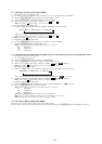
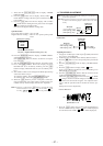
8. Press the [YES] button once to display “LD 0.9 mW $ ”.
Check that the reading of the laser power meter become 0.85
to 0.91 mW.
9. Press the [YES] button once more to display “LD 7.0 mW $
”. Check that the reading the laser power meter and digital
voltmeter satisfy the specified value.
Note down the digital voltmeter reading value.
Specified Value :
Laser power meter reading: 7.0 ± 0.2 mW
Digital voltmeter reading : Value on the optical pick-up label
±10%
10. Press the
[MENU/NO] button to display “LDPWR CHECK”
and stop the laser emission.
(The [MENU/NO] button is effective at all times to stop the
laser emission.)
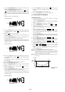
11. Turn the [AMS] knob to display “Iop Write”(C28).
12. Press the [YES] button. When the display becomes
Ref=@@@.@ (@ is an arbitrary number), press the [YES]
button to display “Measu=@@@.@” (@ is an arbitrary num-
ber).
13. The numbers which can be changed will blink. Input the Iop
value noted down at step 9.
To select the number : Turn the
[AMS] knob.
To select the digit : Press the [AMS] knob.
14. When the [YES] button is pressed, “Complete!” will be dis-
played momentarily. The value will be recorded in the non-
volatile memory and the display will become “Iop Write”.
Note 1: After step 4, each time the [YES] button is pressed, the display
will be switched “LD 0.7 mW $ ”, “LD 6.2 mW $ ”, and
“LD Wp $ ”. Nothing needs to be performed here.
±
≠
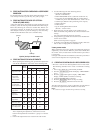
KMS260A
27X40
B0825
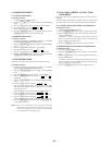
lOP=82.5 mA in this case
lOP (mA) = Digital voltmeter reading (mV)/1 (
Ω
)
(Optical pick-up label)
±
≠
±
≠
±
≠
11. TRAVERSE ADJUSTMENT
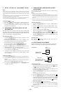
Connection :
Adjusting Procedure :
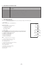
1. Connect an oscilloscope to CN110 pin 3 (TEO) and CN110
pin 1 (VC) on the BD board.
2. Load a disc (any available on the market). (Refer to Note 1)
3. Press the ) button to move the optical pick-up outside the
pit.
4. Turn the [AMS] knob to display “EF MO ADJUS”
(C10).
5. Press the [YES] button to display “EFB = MO-R”.
(Laser power READ power/Focus servo ON/tracking servo
OFF/spindle (S) servo ON)
6. Turn the
[AMS] knob so that the waveform of the
oscilloscope becomes the specified value.
(When the [AMS] knob is turned, the of “EFB=
” changes and the waveform changes.) In this adjustment,
waveform varies at intervals of approx. 2%. Adjust the wave-
form so that the specified value is satisfied as much as pos-
sible.
(Read power traverse adjustment)
Traverse Waveform
7. Press the [YES] button and save the result of adjustment to
the non-volatile memory (“EFB = SAV” will be displayed
for a moment. Then “EFB = MO-W” will be displayed).
+
–
oscilloscope
(DC range)
V: 0.1 V/div
H: 10 ms/div
BD board
CN110 pin
3
(TEO)
CN110 pin
1
(VC)
[]
±
≠
±
≠
±
≠
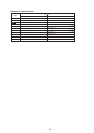
+
–
oscilloscope
(DC range)
10 pF
330 k
Ω
CN110 pin
3
(TEO)
CN110 pin
1
(VC)
BD board
Note 1:Data will be erased during MO reading if a recorded disc is
used in this adjustment.
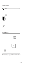
Note 2:If the traverse waveform is not clear, connect the oscilloscope
as shown in the following figure so that it can be seen more
clearly.
A
B
VC
Specification A = B