


– 28 –
±
≠
±
≠
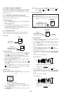
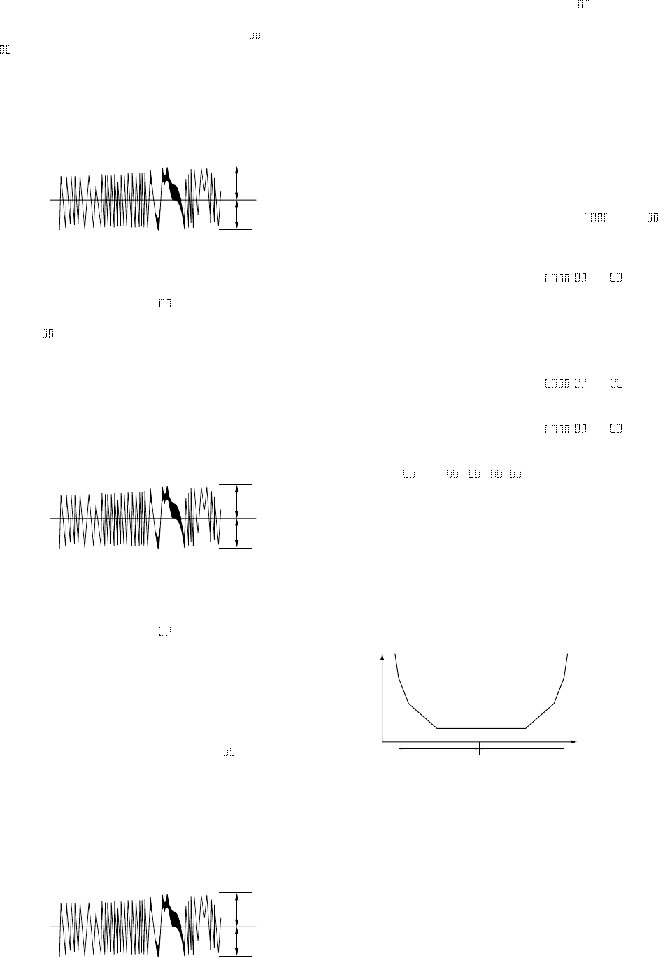
8. Turn the [AMS] knob so that the waveform of the
oscilloscope becomes the specified value.
(When the [AMS] knob is turned, the of “EFB-
” changes and the waveform changes.) In this adjustment,
waveform varies at intervals of approx. 2%. Adjust the wave-
form so that the specified value is satisfied as much as pos-
sible.
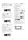
(Write power traverse adjustment)
Traverse Waveform
9. Press the [YES] button, and save the adjustment results in the
non-volatile memory. (“EFB = SAV” will be displayed for
a moment)
10. “EFB = MO-P” will be displayed.
The optical pick-up moves to the pit area automatically and
servo is imposed.
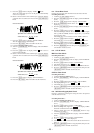
11. Turn the [AMS] knob until the waveform of the os-
cilloscope moves closer to the specified value.
In this adjustment, waveform varies at intervals of approx. 2%.
Adjust the waveform so that the specified value is satisfied as
much as possible.
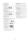
Traverse Waveform
12. Press the [YES] button, and save the adjustment results in the
non-volatile memory. (“EFB = SAV” will be displayed for
a moment.)
Next “EF MO ADJUS” is displayed. The disc stops rotating
automatically.
13. Press the [EJECT] button and take out the disc.
14. Load the check disc (MD) TDYS-1.
15. Turn the [AMS] knob to display “EF CD ADJUS”
(C12).
16. Press the [YES] button to display “EFB = CD”. Servo is
imposed automatically.
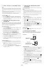
17. Turn the [AMS] knob so that the waveform of the
oscilloscope moves closer to the specified value.
In this adjustment, waveform varies at intervals of approx. 2%.
Adjust the waveform so that the specified value is satisfied as
much as possible.
Traverse Waveform
±
≠
±
≠
±
≠
§
18. Press the
[YES] button, display “EFB = SAV” for a mo-
ment and save the adjustment results in the non-volatile
memory.
Next “EF CD ADJUS” will be displayed.
19. Press the [EJECT] button and take out the disc.
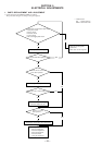
12. FOCUS BIAS ADJUSTMENT
Adjusting Procedure :
1. Load the continuously-recorded disc. (Refer to 5. Creating
Continuously-Recorded Disc)
2. Turn the [AMS] knob to display “CPLAY MODE”
(C29).
3. Press the [YES] button to display “CPLAY MID”.
4. Press the [MENU/NO] button when “C = AD = ” is
displayed.
5. Turn the [AMS] knob to display “FBIAS ADJUS”
(C13).
6. Press the [YES] button to display “ / a = ”.
The first four digits indicate the C1 error rate, the two digits
after [/] indicate ADER, and the 2 digits after [a =] indicate
the focus bias value.
7. Turn the [AMS] knob clockwise and find the focus
bias value at which the C1 error rate becomes about 200 (Re-
fer to Note 2).
8. Press the [YES] button to display “ / b = ”.
9. Turn the [AMS] knob counterclockwise and find the
focus bias value at which the C1 error rate becomes about 200.
10. Press the [YES] button to display “ / c = ”.
11. Check that the C1 error rate is below 50 and ADER is 00.
Then press the [YES] button.
12. If the “( )” in “ - - ( )” is above 20, press the [YES]
button.
If below 20, press the [MENU/NO] button and repeat the ad-
justment from step 2.
13. Press the [EJECT] button and take out the disc.
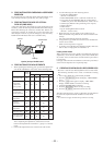
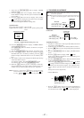
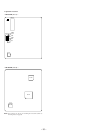
Note 1: The relation between the C1 error and focus bias is as shown in
the following figure. Find points A and B in the following figure
using the above adjustment. The focal point position C is auto-
matically calculated from points A and B.
Note 2: As the C1 error rate changes, perform the adjustment using the
average vale.
§
±
≠
±
≠
±
≠
±
≠
C1 error
about
200
B
C A Focus bias value
(F. BIAS)
A
B
VC
Specification A = B
A
B
VC
Specification A = B
§
A
B
VC
Specification A = B