


– 18 –
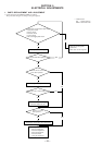
5. SELECTING THE TEST MODE
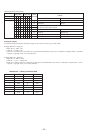
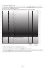
There are 31 types of test modes as shown below. The groups can be switched by turning the [AMS] knob. After selecting the
group to be used, press the [YES] button. After setting a certain group, turning the [AMS] knob switches between these modes.
Refer to “Group” in the table for details can be selected.
All items used for servicing can be treated using group S. So be carefully not to enter other groups by mistake.
±
≠
±
≠
Display
TEMP CHECK
LDPWR CHECK
EF MO CHECK
EF CD CHECK
FBIAS CHECK
S curve CHECK
VERIFY MODE
DETRK CHECK
TEMP ADJUS
LDPWR ADJUS
EF MO ADJUS
EF CD ADJUS
FBIAS ADJUS
EEP MODE
MANUAL CMD
SVDATA READ
ERR DP MODE
SLED MOVE
ACCESS MODE
0920 CHECK
HEAD ADJUST
CPLAY 2MODE
CREC 2MODE
ADJ CLEAR
AG Set (MO)
AG Set (CD)
Iop Read
Iop Write
530 ******
CPLAY MODE
CREC MODE
Contents
Temperature compensation offset check
Laser power check
Traverse (MO) check
Traverse (CD) check
Focus bias check
S letter check
Non-volatile memory check
Detrack check
Temperature compensation offset adjustment
Laser power adjustment
Traverse (MO) adjustment
Traverse (CD) adjustment
Focus bias adjustment
Non-volatile memory control
Command transmission
Status display
Error history display, clear
Sled check
Access check
Outermost circumference check
Head position check
Same functions as CPLAY MODE
Same functions as CREC MODE
Initialization of non-volatile memory of adjustment value
Auto gain output level adjustment (MO)
Auto gain output level adjustment (CD)
IOP data display
IOP data write
Microprocessing version display
Continuous play mode
Continuous recording mode
No.
C01
C02
C03
C04
C05
C06
C07
C08
C09
C10
C11
C12
C13
C14
C15
C16
C17
C18
C19
C20
C21
C22
C23
C24
C25
C26
C27
C28
C29
C30
C31
Mark
(X)
(X)
(X)
(X) (!)
(X)
(X)
(X)
(X)
(X)
(X)
(X)
(X)
Group (
*
)
CS
CS
CS
CS
CS
C
C
C
AS
AS
AS
AS
AS
D
D
D
S
D
D
D
D
D
D
AS
AS
AS
CS
AS
CS
CASD
CASD
Group (
*
)
C: Check
S: Service
A: Adjust
D: Develop
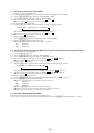
• For details of each adjustment mode, refer to “5. Electrical Adjustments”.
For details of “ERR DP MODE”, refer to “Self-Diagnosis Function” on page 2.
• If a different mode has been selected by mistake, press the [MENU/NO] button to release that mode.
• Modes with (X) in the Mark column are not used for servicing and therefore are not described in detail. If these modes are set acciden-
tally, press the [MENU/NO] button to release the mode immediately. Be especially careful not to set the modes with (!) as they will
overwrite the non-volatile memory and reset it, and as a result, the unit will not operate normally.