


1-23
MVE-8000A
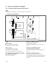
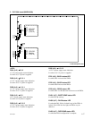
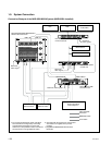
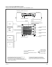
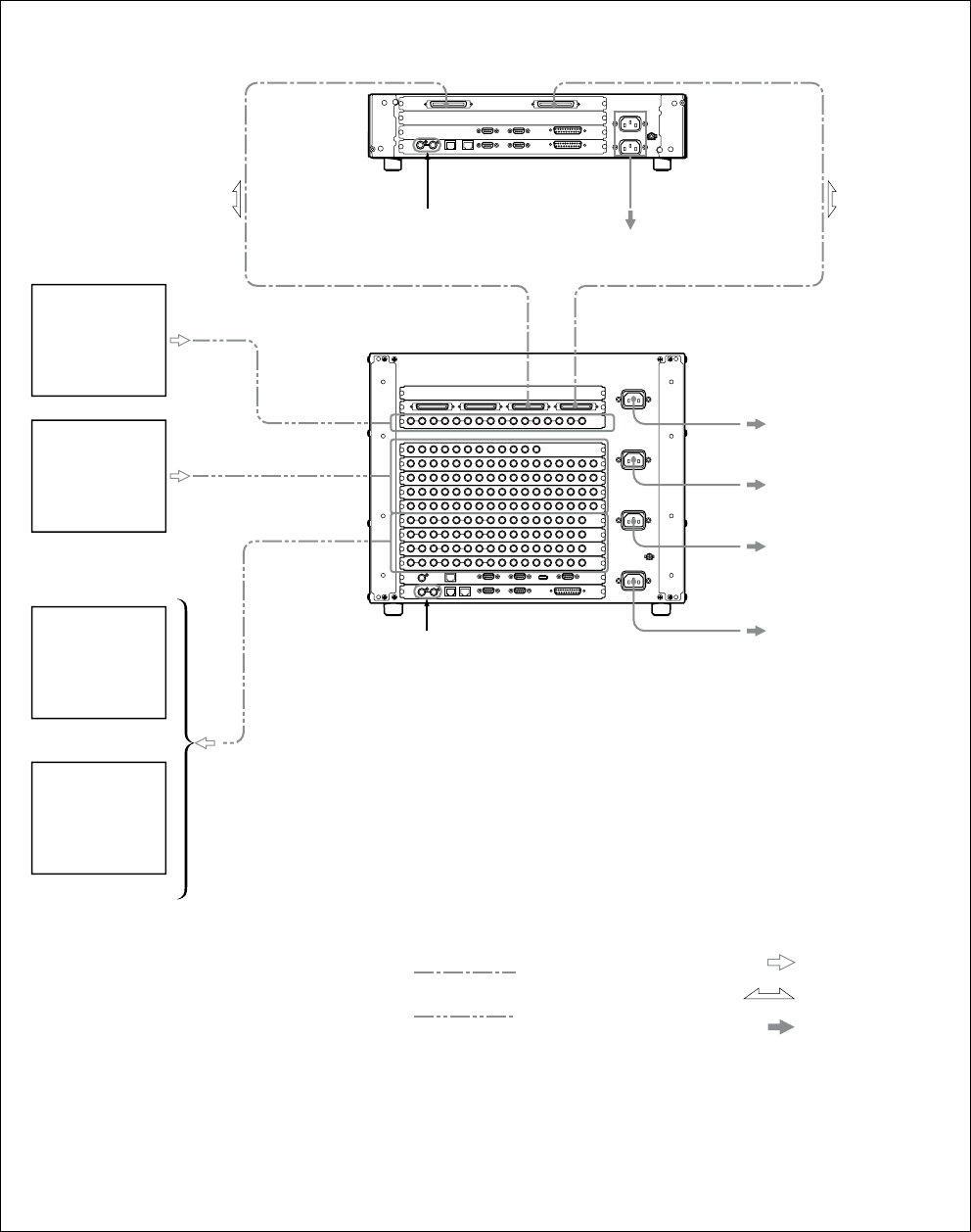
Flow of Video Signals (MKE-8020A Installed)
The figure below shows the flow of video signals in a MVS-8000/8000A system.
SWITCHER B
DME 1B
MONITOR
OUTPUT 1-8
OUTPUTS 1-48
PRIMARY INPUTS 1-80
DME 1A
SWITCHER A
MVE-8000A-C DME Processor Pack
Reference video signal
c)
Monitor
Reference video signal
c)
100 to 240 V AC power supply
a)
Camera,
VTR,
routing
switcher
100 to 240 V AC power
supply
b)
100 to 240 V AC power
supply
b)
Monitor
VTR
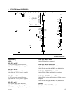
MVS-8400/8300/8200/8000/8000A-C
Switcher Processor Pack
Cable with BNC connectors
AC power supply
Video input signal
Video output signal
Video/key signal
a)
b)
For the AC power cord of this unit, refer to Section “1-2-2.
Recommended Power Cord” in this manual.
For the AC power cord of the MVS-8000/8000A, refer to
“Accessories not supplied” in the MVS-8400/8300/8200/8000/
8000A-C Operation Manual.
c)
d)
Terminate with the supplied 75 Z terminators.
Terminators are supplied in the product package.
Supplied with MKE-8020A MVS Interface Board Set.
100 to 240 V AC power
supply
b)
100 to 240 V AC power
supply
b)
MDR 68-pin cable
d)