


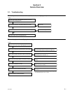
1-20
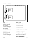
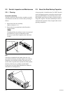
MVE-8000A
<Connector>
CN1501 (C1) : ISP common connector
Used for writing a program in the JTAG device with ISP in
the production process.
<TEST terminals>
E201 (F1), E301 (E1), E401 (G2), E501 (A6),
E502 (A1), E503 (D6), E504 (D3), E505 (G5),
E506 (F3) : GND terminals
Used as ground terminals when measuring voltages on the
check terminals.
TP401 (F1), TP501 (E1) :
++
++
+3.3 V check terminal
+3.3 V measuring terminal.
TP301 (D1), TP502 (D1) :
++
++
+2.5 V check terminal
+2.5 V measuring terminal.
TP201 (E1), TP503 (E1) :
++
++
+1.5 V check terminal
+1.5 V measuring terminal.
TP504 (E1) :
++
++
+12 V check terminal
+12 V measuring terminal.
TP601 (D2) : Check terminal
Used for design purpose.
TP801 (A5) : CK (clock) signal check terminal
Used for checking the CK signal from the motherboard.
TP802 (A5) : FD signal check terminal
Used for checking the FD signal from the motherboard.
TP803 (A5) : CKX (control timing) signal check
terminal
Used for checking the CKX signal from the motherboard.
TP804 (A5) : HD (horizontal sync) signal check
terminal
Used for checking the HD signal from the motherboard.
TP805 (A5) : VD (vertical sync) signal check
terminal
Used for checking the VD signal from the motherboard.
TP1101 (D1), TP1102 (D1), TP1103 (D1),
TP1104 (D1) : DBG0 - DBG3 check terminals
Used for design purpose.
<LEDs on the CPU-DR module>
Refer to <LEDs on the CPU-DR module> in “1. CA-
54CFC Board”.
<Switches on the CPU-DR module>
Refer to < Switches on the CPU-DR module> in “1. CA-
54CFC Board”.
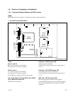
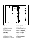
[IF-961 board]
<LEDs>
D1 (E1) :
++
++
+12 V
+12 V power supply status indication.
Lights when the +12 V power is supplied.
If this LED does not light, the fuse may have blown.
D2 (G1) :
++
++
+3.3 V
+3.3 V power supply status indication.
Lights when the +3.3 V power is supplied.
D3 (G2) :
++
++
+2.5 V
+2.5 V power supply status indication.
Lights when the +2.5 V power is supplied.
D4 (G3) :
++
++
+1.5 V
+1.5 V power supply status indication.
Lights when the +1.5 V power is supplied.
D5 (B1) : BUS A
Used for design purpose. (Not lid in normal operation)
D6 (B1) : BUS B
Used for design purpose. (Not lid in normal operation)
D7 (B1) : READ
Used for design purpose. (Not lid in normal operation)
D8 (D1) : DBG 7 A
Used for design purpose. (Not lid in normal operation)
D9 (D1) : DBG 6 A
Used for design purpose. (Not lid in normal operation)
D10 (D1) : DBG 5 A
Used for design purpose. (Not lid in normal operation)
D11 (D1) : DBG 4 A
Used for design purpose. (Not lid in normal operation)
D12 (G1) : BOOT DONE
Lights when booting is completed.