


1-13
MVE-8000A
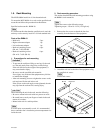
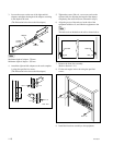
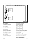
1-8. Checks on Completion of Installation
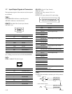
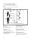
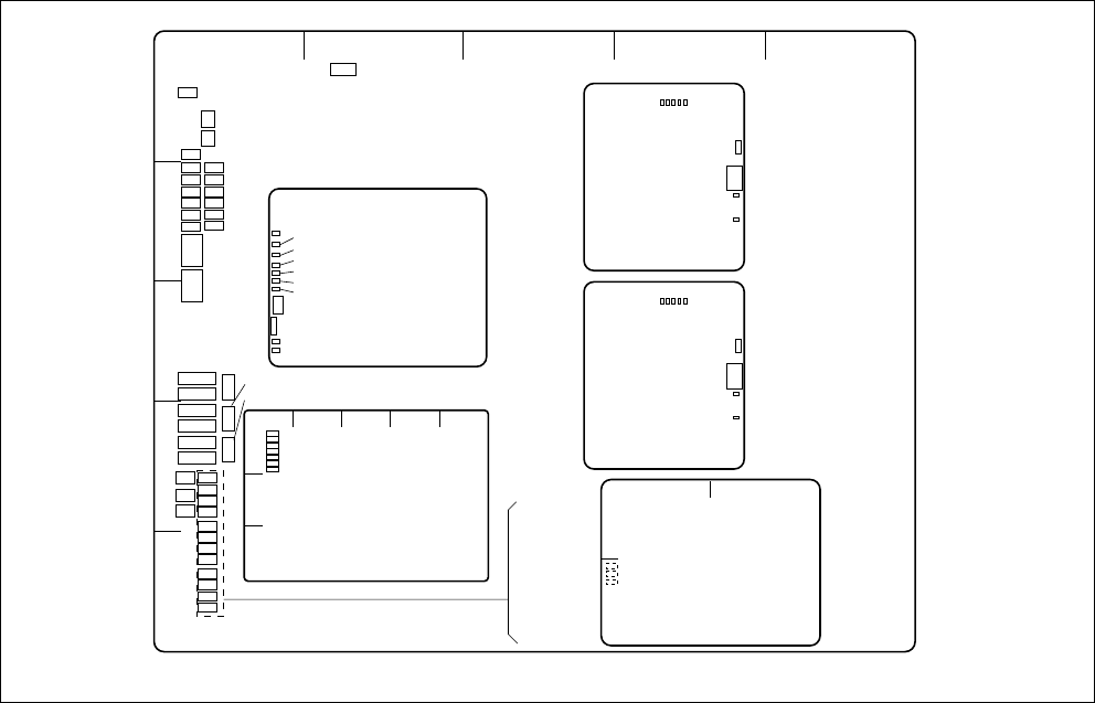
1-8-1. On-board Switches Setting and LED Functions
n
The number shown in parentheses ( ) indicates the address on the circuit board.
1. CA-54CFC board (MVE-8000A)
<LED>
D4 (A-1) :
++
++
+3.3 V
++
++
+3.3 V power supply status indication.
Lit when the +3.3 V power is supplied.
D5 (A-2) :
++
++
+12 V
+12 V power supply status indication.
Lit when the +12 V power is supplied.
If this LED does not light, the fuse may have blown.
D101, D102, D103, D104 (A-4), ND101 (A-3), ND102
(A-4) :
MAIN CPU status LED
Main CPU status indication.
A side/Component side
1
2
3
4
5
AB C D E
ND101
ND102
ND901
ND902
ND1101
ND1102
D409
D410
D1002
D1001
D1201
D1202
D101
D102
D103
D104
D901
D902
D903
D904
D1101
D1102
D1103
D1104
D4
D5
D1303
D601
D602
D704
D701
S101
S102
S103
S104
S901
S1101
S402
S401
S403
TP1301
G
F
E
D
C
B
A
654321
D12
D18
D19
D10
D13
D14
D15
D16
D17
SW2
SW1
F
E
D
C
B
A
12345
DI1
DI4
DI2
DI3
DI6
DI7
DI8
SW1
SW2
F
E
D
C
B
A
12345
DI1
DI4
DI2
DI3
DI6
DI7
DI8
SW1
SW2
ABCDE
1
2
3
D3
D6
D7
D1
D4
D2
D5
S902
S1102
CPU-DR
Module
(MAIN CPU)
DIF-130
(PC CARD)
CPU-DK
Module
(COM CPU-1)
CPU-DK
Module
(COM CPU-2)
D100
D101
D200
A
B
12
SG-272
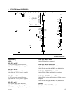
D409 (A-2) : RESET status LED
System reset status indication.
Lit when S401 is pressed or the power voltage drops to
+3.3 V.
D410 (A-2) : CPU RESET status LED
CA-54CFC board reset status indication.
Lit when S402 is pressed or the power voltage drops to
+3.3 V.
D601 (A-2) : REF EXT status LED
REF IN signal presence/absence status indication.
Lit when the REF signal is input to the REF IN connector.
Not lit when the REF signal is not input to the REF IN
connector.