


1-18
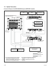
MVE-8000A
<LED on the CPU-DR module> (C-3) and (C-7)
Refer to <LED on the CPU-DR module> in “1. CA-54
CFC Board”.
<Switch on the CPU-DR module> (C-3) and (C-7)
Refer to <Switch on the CPU-DR module> in “1. CA-54
CFC Board”.
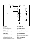
D1004 (A-7) : SYSTEM status LED
Lit when configuration is complete and FPGA reset is also
complete. If the LED does not light, the FPGA may be
defective.
D1101 (A-7) : DGB 7 A status LED
Used for design purpose.
D1102 (A-7) : DGB 6 A status LED
Used for design purpose.
D1103 (A-7) : DGB 5 A status LED
Used for design purpose.
D1104 (A-7) : DGB 4 A status LED
Used for design purpose.
D1201 (A-4) : DGB 7 B status LED
Used for design purpose.
D1202 (A-4) : DGB 6 B status LED
Used for design purpose.
D1203 (A-4) : DGB 5 B status LED
Used for design purpose.
D1204 (A-4) : DGB 4 B status LED
Used for design purpose.
ND1101 (A-6), ND1102 (A-6) : STATUS A LED
The status indication of the CPU A on the DVP-30A
board.
ND1201 (A-3), ND1202 (A-3) : STATUS B LED
The status indication of the CPU B on the DVP-30A board.
<Switch>
S801 (A-6) : CPU A CONFIG switch
Used for maintenance purpose.
S901 (A-4) : CPU B CONFIG switch
Used for maintenance purpose.
S1101 (A-7) : SETUP A switch
Used for maintenance purpose.
S1201 (A-4) : SETUP B switch
Used for maintenance purpose.