


24
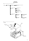
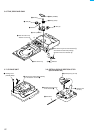
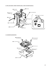
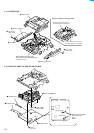
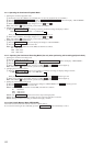
3-12. BASE UNIT (MBU-5A) AND BD (MD) BOARD
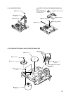
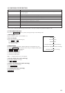
• Note for installation of Slider (CAM)
Set the shaft of Cam gear to
be at the position in the figure.
Set the shaft of Lever (O/C) to
be at the position in the figure.
6
Slider (CAM)
2
Bracket (GUIDE L)
5
Bracket (GUIDE R)
4
Two screws
(BTP 2.6x6)
1
Two screws
(BTP 2.6x6)
3
Leaf spring
A
When attaching the slider (cam),
this part of the over write head should
be inside arrow
A
.
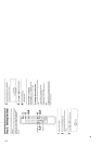
3-11. SLIDER (CAM)
2
Base unit (MBU-5A)
1
Three screws
(BTP 2.6x6)
5
Screw
(M 1.7x4)
7
BD (MD) board
6
Flexible board
7
Flexible board
CN104
CN101
CN110
Spindle motor
3
Remove the two solders.
Read wire's color
Red : +
Black :
-
4
Remove the two solders.
Sled motor
-
+