


Setting up the Keypad
30
US
It is recommended that you test all the components before
you finish with the installation of the entire system in
each zone so as not to encounter any problems after the
installation is completed. Check to see if the Main Unit,
the installed components, and the Keypad operate
properly by testing each operation.
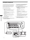
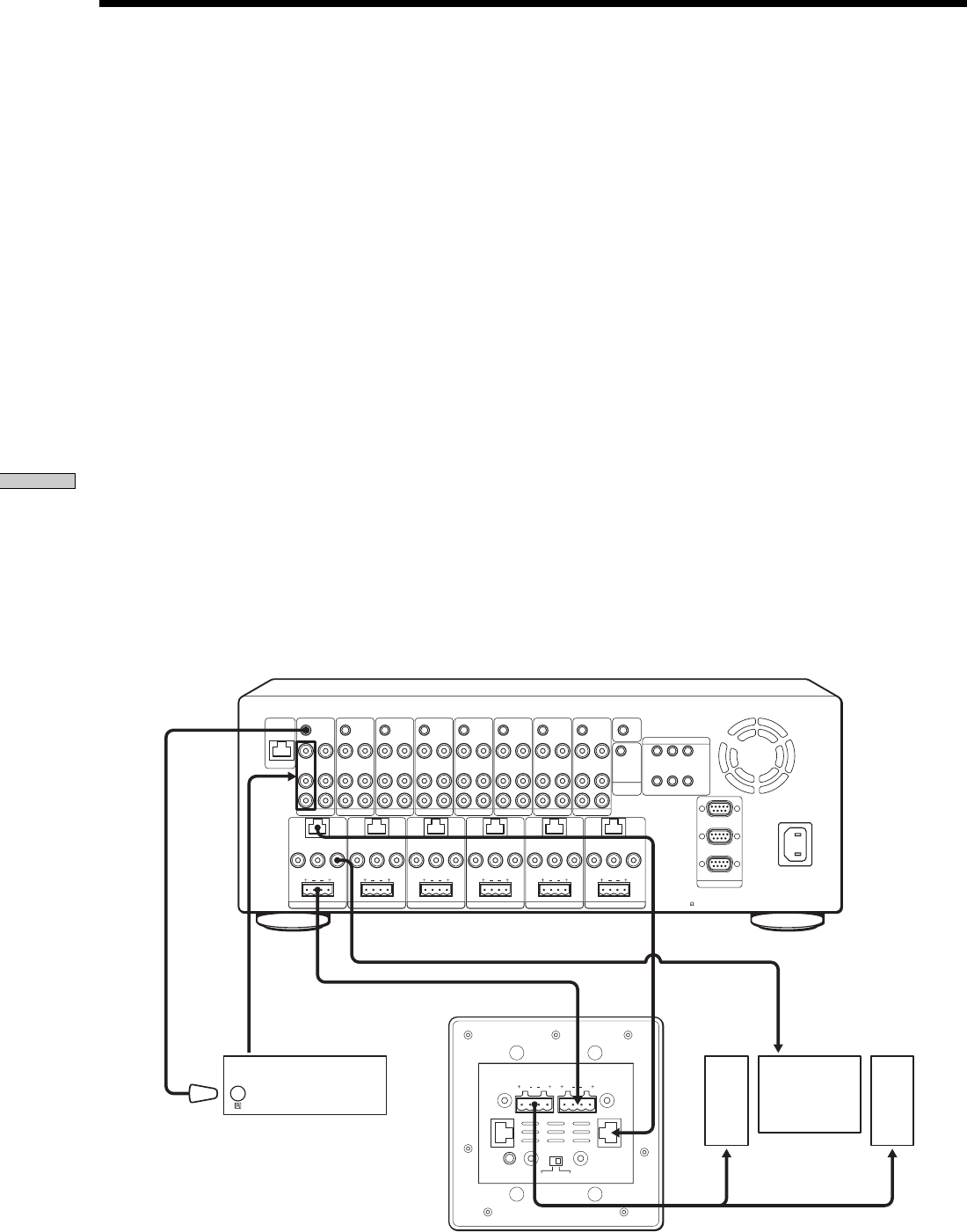
1 Check the following connections.
- All the Keypads are connected to the Main Unit via CAT5
cables.
- An audio or a video component is connected between
AUDIO IN Left/Right and VIDEO IN of each SOURCE
connection jack.
- A display (output component) is connected to VIDEO OUT
at each ZONE connection jack.
- Speakers are connected to SPEAKERS at each ZONE
connection jack.
- An IR emitter is connected to IR OUT of each SOURCE
connection jack, and is placed near the IR sensor of the
source component.
- AC power cords for the Main Unit and the other
components are plugged in.
2 Turn on the Main Unit.
3 Select ZONE 1 by pressing the ZONE button on the
front panel of the Main Unit.
Testing the Components
4 Select SOURCE 1 by pressing the SELECT SOURCE
button on the front panel of the Main Unit.
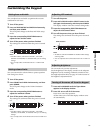
5 Turn on the Keypad in zone 1.
6 Select SOURCE 1 by pressing the SELECT button on
the Keypad. Then, check the following.
- Power control
Press POWER to turn the Keypad on or off.
- Volume adjustment
Press VOLUME +/– to adjust the volume.
- Muting
Press MUTING to mute the speaker output.
- Playback operation
Press the Play, Stop, Pause, and ./> buttons on the
Keypad to confirm that the source component operates
properly.
- Remote control operation
Check that the remote control of the SOURCE 1 component
works by pressing any command button while pointing
the Remote Control toward the IR sensor of the Keypad.
Then check that the SOURCE 1 component operates
properly using the remote control.
7 Perform the test in each zone from zone 1 through
zone 6 by repeating Steps 3 to 6.
L
VIDEO IN
IR OUT
VIDEO OUT
AUDIO IN
KEYPAD
FIXED
PRE OUT
LR
RL
VIDEO OUT
SPEAKERS
(
CLASS 2 WIRING
)
AUDIO OUT
R
SOURCE 1
ANTENNA
ZONE 1
L
VIDEO IN
IR OUT
VIDEO OUT
AUDIO IN
AUDIO OUT
R
SOURCE 2
L
VIDEO IN
IR OUT
VIDEO OUT
AUDIO IN
AUDIO OUT
R
SOURCE 3
L
VIDEO IN
IR OUT
VIDEO OUT
AUDIO IN
AUDIO OUT
R
SOURCE 4
L
VIDEO IN
IR OUT
VIDEO OUT
AUDIO IN
AUDIO OUT
R
SOURCE 5
L
VIDEO IN
IR OUT
VIDEO OUT
AUDIO IN
AUDIO OUT
R
SOURCE 6
L
VIDEO IN
IR OUT IR OUT
COMMON
VIDEO OUT
AUDIO IN
AUDIO OUT
R
SOURCE 7
L
123
VIDEO IN
IR OUT
VIDEO OUT
AUDIO IN
AUDIO OUT
R
SOURCE 8
RS232C
~AC IN
STR
CONTROL
A1 II
12V TRIGGER
KEYPAD
FIXED
PRE OUT
LR
RL
VIDEO OUT
SPEAKERS
(
CLASS 2 WIRING
)
ZONE 2
KEYPAD
FIXED
PRE OUT
LR
RL
VIDEO OUT
SPEAKERS
(
CLASS 2 WIRING
)
ZONE 3
KEYPAD
FIXED
PRE OUT
LR
RL
VIDEO OUT
SPEAKERS
(
CLASS 2 WIRING
)
ZONE 4
KEYPAD
VARIABLE
PRE OUT
VARIABLE
PRE OUT
LR
RL
VIDEO OUT
SPEAKERS
(
CLASS 2 WIRING
)
ZONE 5
KEYPAD
LR
RL
VIDEO OUT
SPEAKERS
(
CLASS 2 WIRING
)
ZONE 6
456
DVP
AUX
SPEAKERS IMPEDANCE
USE 4-16
IR IN
OUT
R
TO SPEAKERS
L
IN
R
FROM AMPLIFIER
MODE
SUB
L
MAIN
DVD player
Ke
y
pad
SP TV
SP
IR emitter