


1-13
DFS-700/700P
Chapter 2 Location and Function of
Parts and Controls
2-14
Chapter 2 Location and Function of Parts and Controls
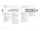
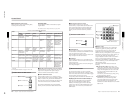
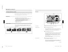
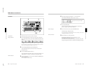
1 PGM OUT (program output) connectors
These output the final program output, that is, the
video to which effects have been applied. Connect to
VTR (recorder) and program monitor video input
connectors. The following four types of output are
provided, each with two channels (1 and 2).
SDI (BNC): Output serial digital signals (270 MHz).
COMPOSITE (BNC): Output composite video
signals.
COMPONENT (BNC): Output Betacam format
component video signals (Y, R–Y, B–Y).
S VIDEO (4-pin): Output S-video (Y/C separation)
signals.
You can use all four formats simultaneously. The same
signals are output from connectors 1 and 2.
2 VIDEO INPUT connectors
These input video camera and VTR (player) video
signals. The connectors are in four groups, as follows.
•SDI INPUT 1 to 4, (OPTION) 5 to 8 (BNC)
•COMPONENT 5/1, 6/2, 7/3, 8/4 (BNC)
•COMPONENT/COMPOSITE (OPTION) 5 to 8
(BNC)
•S VIDEO (OPTION) 5 to 8 (4-pin)
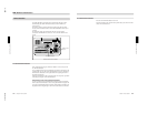
SDI INPUT 1 to 4, (OPTION) 5 to 8 (BNC-type)
Input serial digital signals (270 MHz).
Connectors 5 to 8 can only be used when the optional
BKDF-701 SDI and Component Input Board is
installed.
The input signals to these connectors must be
synchronized to this unit.
COMPONENT 5/1, 6/2, 7/3, 8/4 (BNC-type)
Input Betacam format component video signals.
Y: Input the luminance (Y) signal.
R–Y: Input the R–Y color difference signal.
B–Y: Input the B–Y color difference signal.
The input signals to these connectors must be
synchronized to this unit. Therefore, when inputing
from a VTR, the signal must come through a time base
corrector.
The 8/4 column of connectors can be changed to RGB
input connectors by a setup menu operation. In this
case, connect G (with sync), R, and B signals to Y, R–
Y, and B–Y respectively.
When the optional BKDF-702/702P Y/C and
Composite Input Board is installed, you can select in
the setup menu whether to use the 5/1, 6/2, 7/3, and
8/4 connectors for component inputs 5 to 8 or
component inputs 1 to 4.
COMPONENT/COMPOSITE (OPTION) 5 to 8
(BNC-type)
These connectors can be used by installing either of
the optional BKDF-701 and BKDF-702/702P boards.
When the BKDF-701 board is installed, connect
Betacam format component video signals. When the
BKDF-702/702P board is installed, connect composite
video signals. The signals can be input from a VTR
with no time base corrector. When using the BKDF-
701 to input signals from a VTR, they must come
through a time base corrector.
S VIDEO (OPTION) 5 to 8 (4-pin)
Input S-video (Y/C separation) signals. These
connectors can only be used when the optional BKDF-
702/702P board is installed. The signals can be input
from a VTR with no time base corrector.
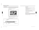
3 EDITOR connector (9-pin)
Use this connector when controlling this unit with an
editor (PVE-500, BVE-2000 series, or other editing
control unit). Using an optional 9-pin remote control
cable, connect to the 9-pin control connector of the
editor.
4 PANEL connector (25-pin)
With the supplied 25-pin control cable, connect to the
25-pin connector of the control panel.
5 TALLY connector (25-pin)
Tally signals are output from this connector when the
signal input to a VIDEO INPUT connector is selected
on the control panel. Connect to the input signal
sources (video cameras etc.). The outputs are relay
contact signals, with a capacity of 200 mA / 30 V.
6 TERMINAL connector (USB type B)
This is a USB interface connector. Use it when
connecting to a computer for a software version
upgrade.
Connector
Input signal for
BKDF-701
Input signal for
BKDF-702/702P
Y/V Luminance (Y) signal
Composite signal
R–Y Color difference
signal (R–Y)
Not used
B–Y Color difference
signal (B–Y)
Not used
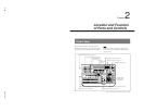
Processor Unit
Chapter 2 Location and Function of
Parts and Controls
Chapter 2 Location and Function of Parts and Controls
2-15
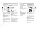
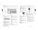
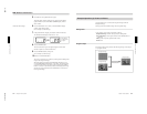
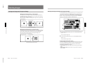
7 CLEAN OUT connector (BNC-type)
Outputs serial digital signals (270 MHz). Using the
setup menu, you can select the output from the
following three signals.
CLEAN OUT: The program output signal, without
the downstream key inserted.
PVW OUT: The signal output is the same as the
program output after completion of the effect
transition. The title area can also be shown.
KEY OUT: This outputs a key signal corresponding
to the shape of a selected effect. Use it as the key
source input to another device.
8 PVW (preview) connector (BNC-type)
This is an analog composite preview output. The signal
output is the same as the program output after
completion of the effect transition. It is not possible to
include the title area.
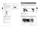
9 BLACK BURST OUT 1 to 3 connectors (BNC-
type)
These output the black burst signals generated by the
synchronizing signal generator internal to this unit.
When an external synchronizing signal is input to the
REF. VIDEO IN connectors, the black burst signal
output is locked to the external synchronizing signal.
Use the output from these connectors as a reference
synchronizing signal when synchronizing input signal
sources (character generators, etc.), or when
synchronizing this unit with a VTR or editor to
improve the precision of editing.
q; DSK (downstream keyer) KEY IN connectors
(BNC-type) and 75 Ω terminator switch
Input the key source signal for a downstream key,
from a character generator or other device.
When the 75 Ω terminator switch is in the OFF
position, the connectors provide a loop-through
connection; with the key signal input to one connector,
the other provides the same key source signal to
another device. By connecting to an analog component
Y connector on this unit, you can use it as a title key
source.
When not using the loop-through output, the 75 Ω
terminatior switch must be in the ON position.
qa REF. (reference) VIDEO IN connectors (BNC-
type) and 75Ω terminator switch
When using this unit synchronized to an external
signal, input the external reference signal (black burst).
When the 75Ω terminatior switch is in the OFF
position, the connectors provide a loop-through
connection; with the reference signal input to one
connector, the other provides the same reference signal
for another device. When not using the loop-through
output, the 75Ω terminatior switch must be in the ON
position.
qs GPI/T (GPI/trigger) 1 and 2 connectors (BNC-
type)
Input external trigger signals. These are used when
controlling editing with GPI signals or an editor (BVE-
600).
qd U (ground) terminal
Connect this to ground as required.
qf - AC IN connector
With the supplied power cord, connect to the AC
supply.