


5
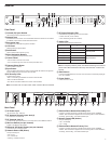
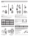
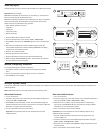
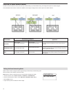
Front Panel
① Infrared (IR) Sync Window
Sends IR signal to the transmitter for sync.
② Network Icon
Illuminates when the receiver is connected with other Shure devices on the network.
IP Address must be valid to enable networked control.
③ Encryption Icon
Illuminates when AES-256 encryption is activated.
④ LCD Panel
Displays settings and parameters.
⑤ Scan Button
Press to find the best channel or group.
⑥ Menu Navigation Buttons
Use to navigate and select parameter menus.
⑦ Control Wheel
• Push to select a channel or menu item
• Turn to scroll through menu items or to edit a parameter value
⑧ Channel Select Button
Press to select a channel.
⑨ Sync Button
Press the sync button while the receiver and transmitter IR windows are aligned to
transfer settings from the receiver to the transmitter.
⑩ RF Diversity LEDs
Indicate antenna status:
• Blue = normal RF signal between the receiver and transmitter
• Red = interference detected
• Off = No RF connection between the receiver and transmitter
Note: the receiver will not output audio unless one blue LED is illuminated.
Receiver
⑪ RF Signal Strength LEDs
Indicate the RF signal strength from the transmitter:
• Amber = Normal (-90 to -70 dBm)
• Red = Overload (greater than -25 dBm)
⑫ Audio LEDs
Indicate average and peak audio levels:
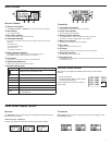
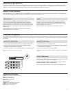
LED Audio Signal Level Description
Red (6) -0.1 dBFS Overload/ limiter
Yellow (5) -6 dBFS
Normal peaks
Yellow (4) -12 dBFS
Green (3) -20 dBFS
Signal PresentGreen (2) -30 dBFS
Green (1) -40 dBFS
Note: In Frequency Diversity mode, simultaneous blinking of the red and
yellow audio LEDs indicates that diversity audio has been routed to this
channel.
⑬ Gain Buttons
Pressthe▲▼gain buttons on the front of the receiver to incrementally adjust gain
from -18 to +42 dB.
⑭ Power Switch
Powers the unit on or off.
ULXD4Q
Digital Wireless Receiver
push
control
ENTER
EXIT
SCAN
power
RF
A B
OL
OL
gainaudio
RF
A B
OL
OL
gainaudio
RF
A B
OL
OL
gainaudio
RF
A B
OL
OL
gainaudio
RX1 RX2 RX3 RX4
IR
sync
sync sync sync
1
7
8
12
14
9
10
11
3
2
5
6
13
4
SEL
SEL SEL
SEL
2
3
7 864
1
5
4 5 4
5
4
5
9
2
3
line
mic
line
mic
line
mic
line
mic
B
A
output 1output 2output 3output 4
PrimarySecondary
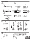
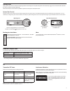
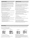
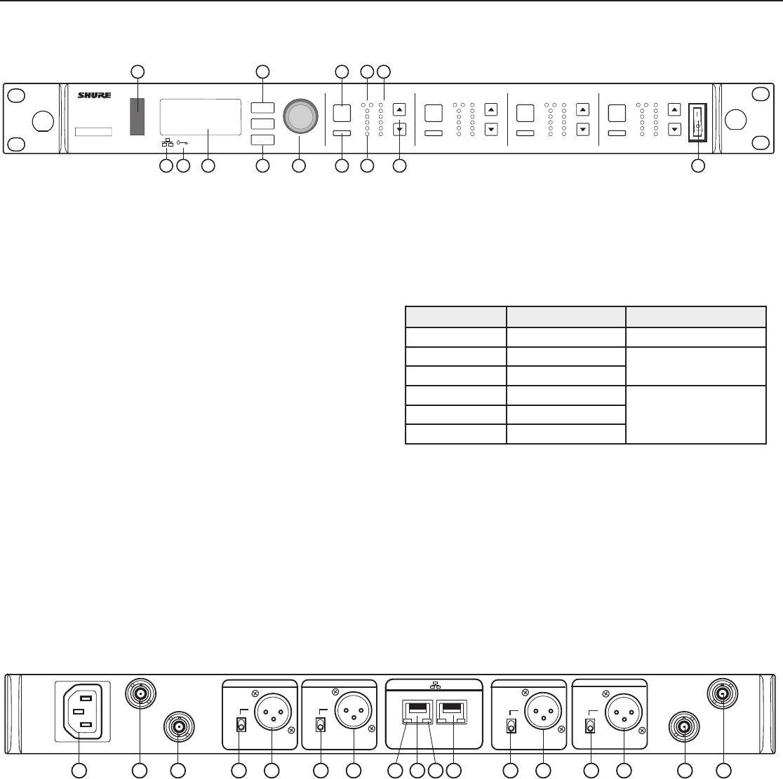
① AC Power Input
IEC Connector, 100 - 240 V AC.
② RF Antenna Diversity Input Jack (2)
For antenna A and antenna B.
③ RF Cascade Jack (2)
Passes the RF signal from Antenna A and Antenna B to one additional receiver.
④ Mic/Line Switch (one per channel)
Applies a 30 dB pad in mic position.
⑤ Balanced XLR Audio Output (one per channel)
Connect to a mic or line level input.
⑥ Network Status LED (Green)
One per network port.
• Off = no link
• On = network link
• Flashing = network link active
⑦ Ethernet/Dante Network Secondary Port
Connect to an Ethernet network to enable remote device control via WWB6
software. Also carries Dante digital audio and control signals for audio distribution,
monitoring, and recording - see Dante Network topic.
⑧ Network Speed LED (Amber)
One per network port.
• Off = 10/100 Mbps
• On = 1 Gbps
⑨ Ethernet/Dante Network Primary Port
Connect to an Ethernet network to enable remote device control via WWB6
software. Also carries Dante digital audio and control signals for audio distribution,
monitoring, and recording - see Dante Network topic.
Back Panel