


11
High Density Mode
High Density mode creates additional bandwidth for more channels in
crowded RF environments. Frequency efficiency is optimized by running
at 1 mW RF transmit power and narrowing the modulation bandwidth,
allowing for the channel spacing to be reduced from 350 kHz to 125 kHz.
Transmitters can be positioned on adjacent channels with unsubstantial
intermodulation distortion (IMD).
High Density mode is ideal for applications where many channels are
needed in a confined area, transmission distances are short, and the
number of available frequencies is limited. Up to 30 meters of range is
available in High Density mode.
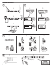
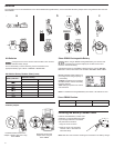
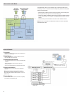
Setting the Receiver to High Density Mode
To set the receiver to High Density mode:
DEVICE UTILITIES > ADVANCED RF > HIGH DENSITY
Use the control wheel to set HIGH DENSITY to ON.
When prompted, sync the transmitter and receiver to enable
HIGH DENSITY
mode.
Note: When the receiver is in
HIGH DENSITY mode, the following indicators
are shown on the receiver display:
• The
HD icon will appear on the receiver display
• The receiver band name will be shown with an "HD" added. (example:
The G50 band will appear as G50HD)
• The transmitter group and channel are assigned letters instead of
numbers (example: G:AA CH:AA)
Best Practices for High Density Mode
• When band planning, position ULX-D High Density channels in a range of
frequencies separated from other devices.
• Use a separate RF zone for ULX-D High Density channels to prevent
intermodulation distortion from other devices.
• During High Density channel scanning, turn on all other transmitters and
move them to their intended position.
• Perform a walk test to verify transmitter range
• If using custom groups, the groups loaded into the receiver must be
compatible with High Density mode
1 + 2 + 3 + 4
1 + 2 + 3 + 4
1 + 2 + 3 + 4
1 + 2 + 3 + 4
1
2
3
4
1 + 2
1 + 2
3 + 4
3 + 4
1
2
3
4
3
4
1 +2
1 +2
1
2
3
4
2
1
3 + 4
3 + 4
1
2
3
4
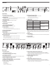
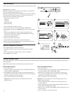
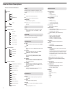
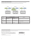
Audio Summing
Audio summing allows the dual and quad receivers to function as a 2 or 4 channel mixer, respectively. All XLR outputs of the selected channels provide the
summed audio. For example, when 1 + 2 is selected (see diagram), the XLR outputs of channels 1 and 2 supply the summed audio of the two channels.
Choosing an Audio Summing Mode
The following Audio Summing mode options are available:
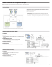
Frequency Diversity
Frequency Diversity is an advanced ULX-D receiver feature that safeguards
against loss of audio signal caused by RF interference or by power loss in a
transmitter.
In Frequency Diversity mode, the signals from two transmitters from a
common audio source are routed to the outputs of 2 receiver channels. In
the event of interference or power loss, the audio from the good channel is
switched to both outputs to preserve the audio signal. Switching between
channels is seamless and inaudible.
When the receiver senses that the signal quality has improved, audio
routing is restored without interrupting the audio signal.
Note: WWB6 software offers an option to selectively lock the diversity audio
source to a specific transmitter (see Wireless Workbench 6 section).
Best Practices for Frequency Diversity
• Use the same microphone type and model for each transmitter
• Place microphones within close proximity to the source
• Use the gain controls to match the output levels for each receiver channel
• If Audio Summing is active, use a Y-cable (Shure AXT652) to connect the
bodypacks to a single audio source to prevent comb filtering
Choosing Diversity Output Routing
The following receiver channel routing output options are available:
•
1 + 2
• 3 + 4 (quad only)
• 1 + 2 / 3 + 4 (quad only)
To enable Frequency Diversity and select a routing option:
DEVICE UTILITIES > FREQ DIVERSITY
Use the control wheel to choose a routing option, and then press ENTER.
Note: Choose
OFF to disable Frequency Diversity.
Frequency Diversity and Encryption
Enabling Encryption while in Frequency Diversity mode provides an
additional layer of protection by only passing audio from the most recently
synced encrypted transmitter for each receiver channel.
3 + 4
1 + 2 / 3 + 4
1 + 2 + 3 + 4
To select an Audio Summing mode:
1 + 2
1. Menu: DEVICE UTILITIES > AUDIO SUMMING
2. Use the control wheel to select an option, and then press Enter.
Note: When set to OFF, Audio Summing is disabled.
Adjusting Gain for Summed Outputs
Use the gain controls for each channel to create the overall mix balance.
The front panel LEDs indicate the audio level for each channel. If an
overload occurs, the red LEDs will illuminate indicating that the internal
limiter is active and the display will show an overload message. To correct,
adjust the overall gain balance.