


27
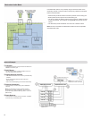
50 Ω
22 µF
22 µF
-30 dB
50 Ω
mic/ line
500 Ω 500 Ω
910k Ω
100 µF
440 pF
1µF
Pad
12dB
Z
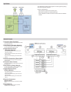
2 2
1
1
3
*
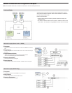
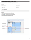
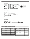
Tables and Diagrams
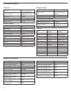
TA4M Connector
Active
Load
5 V DC
Audio Input
Ground
①Ground
②BiasVoltage
③AudioInput
④ActiveLoad
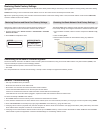
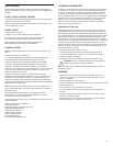
XLR Receiver Output
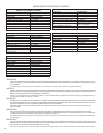
XLR to ¼ Output
Use the following wiring diagram to convert the XLR output to a ¼ output.
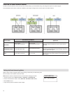
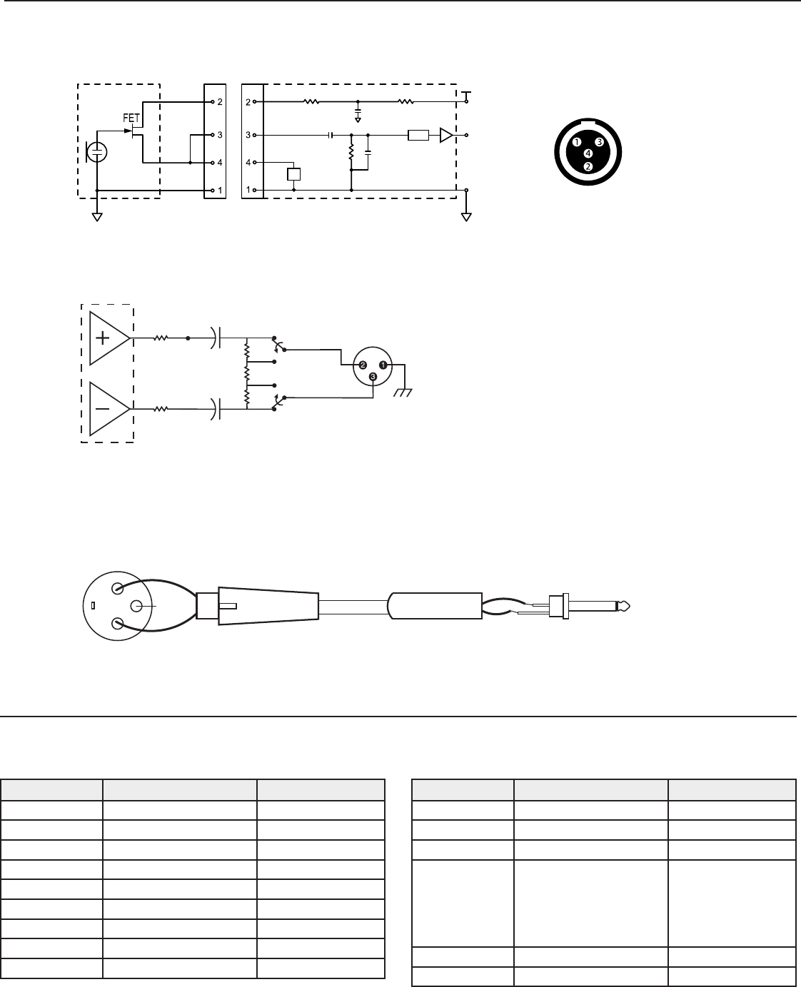
Frequency Range and Transmitter Output Power
Band Frequency Range ( MHz) Power (mW)
G50 470 to 534 1/10/20
G51 470 to 534 1/10/20
G52 479 to 534 1/10
H51 534 to 598 1/10/20
H52 534 to 565 1/10
J50 572 to 636 1/10/20
K51 606 to 670 1/10
L50 632 to 696 1/10/20
L51 632 to 696 1/10/20
Band Frequency Range ( MHz) Power (mW)
P51 710 to 782 1/10/20
R51 800 to 810 1/10/20
JB (Tx only) 806 to 810 1/10
AB (Rx and Tx) 770 to 810
"A" band (770.250-
805.750): 1/10/20
"B" band (806.125-
809.750): 1/10
Q51 794 to 806 1/10/20
X50 925 to 932 1/10
* No Connection