


3
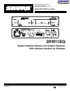
THE DFR11E
Q
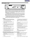
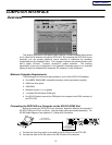
Overview
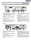
Front Panel
ÊËÌ Í Î Ï Ð Ñ
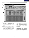
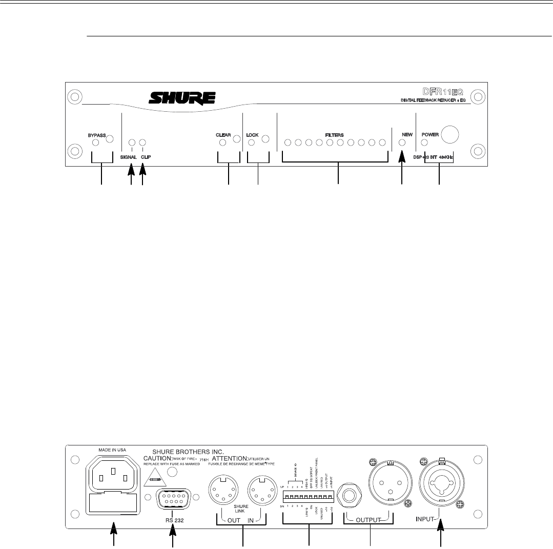
ÊBYPASS Button and LED. Press this button to
suspend feedback reducer operation and remove
filters from the audio path. Does not affect the
graphic equalizer. When the LED illuminates, the
feedback
reducer is bypassed.
Ë SIGNAL LED. Illuminates when input signal is
present.
Intensity varies with input signal level.
Ì CLIP LED. Illuminates when the input signal is
within
6 dB of clipping.
Í CLEAR Filters Button and LED. Press this
recessed button to reset all the feedback filters.
Clears filters even if Lock Filters is enabled. LED
illuminates
as the button is pressed.
Î LOCK Filters Button and LED. Press this button
to lock the filters at their current values. When the
LED is on, the unit will not change or add any
feedback
filters.
Ï FILTERS LEDs (10). Indicate when individual
feedback
filters are active.
When a filter changes or
is
added, the LED flashes, then stays on.
Ð NEW Filter LED. Flashes in unison with the
feedback
filter LEDs when the detector is deploying
a
new feedback filter or changing an existing one.
Ñ POWER
Switch and LED.
Press this button to
turn
the
power on. LED illuminates when unit is powered
on. When the power is off, the unit is bypassed
automatically.
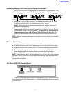
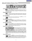
Back Panel
ÎÏÌËÊÍ
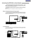
ÊPower Connector with Integral Fuse. Connects
to
AC power. The fuse is
located in the drawer below
the
connector.
Ë 9-Pin RS-232 Port. Connects the unit to a
computer.
For use with DFR11EQ software and for
DSP
firmware upgrades.
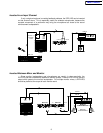
Ì Shure Link Interface. Allows linking of up to 16
DFR11EQs
which may be accessed by computer
.
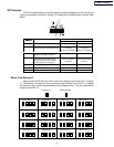
Í
DIP Switches.
See
DIP Switches
.
Î Output Connector—
1
/
4
-Inch & XLR. Active,
cross-coupled, balanced outputs can be used with
balanced or unbalanced inputs. Can be switched
between
+4 dBu/–10 dBV line-level operation by DIP
switch.
1
/
4
-Inch and XLR are driven independently
and either can be balanced or unbalanced without
affecting
the other
.
Ï Input Connector—Combined XLR and
1
/
4
-Inch.
Active
balanced
input can be used with balanced or
unbalanced outputs. Can be switched between +4
dBu/–10
dBV line-level operation by DIP switch.
Main Menu