


5
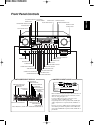
System Connections
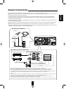
When making system connections, please be certain the AC cord is not plugged into an AC outlet.
When making connections between components, please be sure to connect the white RCA plugs to the L (left) and the red
RCA plugs to the R (right) jacks respectively.
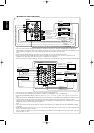
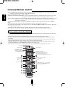
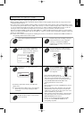
Change the position of the FM indoor antenna until you get the best possible reception of your favorite FM stations.
A 75 Ohm outdoor FM antenna may be used to further improve the reception. Disconnect the indoor antenna before
connecting the outdoor antenna.
Place the AM loop antenna as far as possible from the receiver, TV set, speaker cords and the AC input cord and set it to a
direction for the best reception.
If the reception is poor with the AM loop antenna, an AM outdoor antenna can be used in place of the AM loop antenna.
Make all connections firmly and correctly. Failure to do so can cause loss of sound, noise or damage to the receiver.
If the electricity fails or the AC cord is left unplugged for about two weeks, all operating parameters in the unit’s memory
will be lost. Should this happen, you must enter them again.
SUB
WOOFER
VIDEO 3
VIDEO 4
CD
TAPE/MD
MULTIROOM
VIDEO 3
VIDEO 4
VIDEO 2
VIDEO 3
VIDEO 4
VIDEO 2
VIDEO 3
Y
C
B
C
R
Y
C
B
C
R
VIDEO 2
VIDEO 3
VIDEO 4
DIGI
-
LINK
AC INPUT
120V~60Hz
4A
SWITCHED
120V~60Hz
TOTAL 100W 1A MAX
AC OUTLETS
MODEL NO. R
-
956
AUDIO/VIDEO RECEIVER
SER. NO
MADE IN KOREA
DESIGNED IN USA
C
E85649
29Z3
LISTED
AUDIO EQUIPMENT
This device complies with Part 15 of the FCC Rules.
Operation is subject to the following two conditions:
(1)This device may not cause harmful interference, and
(2)this device must accept any interference received,
including interference that may cause undesired operation.
Manufactured under license from Digital Theater Systems, Inc.
US Pat. No. 5,451,942 and other world-wide patents issues and pending.
“DTS” and “DTS Digital Surrou emarks of Digital Theater
Systems, Inc.
©1996 Digital Theater Systems, Inc. All rights reserved.
Manufactured under license from Dolby Laboratories. “Dolby”, “Pro Logic”
and the double-D symbol are trademarks of Dolby Laboratories.
Confidential Unpublished Works.
©1992-1997 Dolby Laboratories, Inc.
All rights reserved.
6.1-CH
DIRECT
INPUT
FRONT
REAR
REAR
CENTER
FRONT
CENTER
PHONO
CD
AUX
VIDEO 1
VIDEO 2
AM
LOOP
VIDEO 2
VIDEO 1
MONITOR
FRONT
SPEAKERS
(8
Ω
)
REAR
SPEAKERS
(8
Ω
)
REAR
CENTER
SPEAKER
(8
Ω
)
FRONT
CENTER
SPEAKER
(8
Ω
)
ANTENNA
VIDEO 1
6.1 CH
S
-
VIDEO
6.1 CH
VIDEO 1
IN
IN IN
OUT
VIDEO
OUT
TAPE
MON.
VIDEO 1
ROOM 2
GND
VIDEO 1
R R
OUT
OPTICAL
COXIAL
DIGITAL
IN
PRE
OUT
FRONT
CENTER
L R
L R
L R
SUB
WOOFER
FRONT
REAR
REAR
CENTER
TAPE
MON.
L R
LR
LR
ROOM 2
VIDEO 1
OUT
REC
REC
MONITOR
Y
C
B
C
R
MONITOR
COMPONENT
" is a trademark of SRS Labs, Inc."
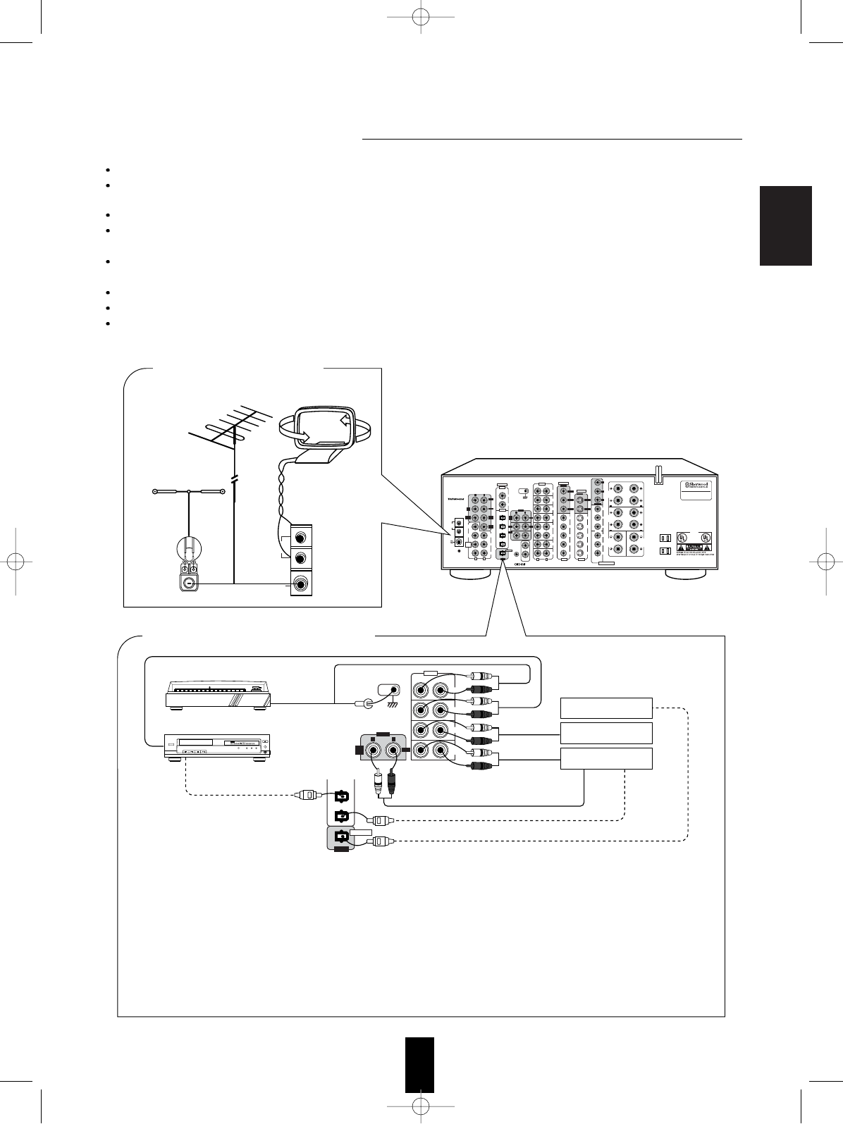
■ CONNECTING ANTENNAS
AM loop antenna
FM
FM
(INDOOR ANTENNA)
(OUTDOOR ANTENNA)
SUPPLIED ADAPTOR
300 ohm
feeder
AM
LOOP
FM
75
Ω
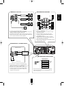
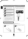
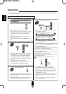
• The AUX jacks may be connected to an additional audio component such as a CD player, a tape deck, etc.
• Connect the TAPE MONITOR IN/OUT jacks to the PLAY(LINE OUT)/REC(LINE IN) jacks of a tape deck or MD recorder.
• The TAPE MONITOR IN/OUT jacks may also be connected to the LINE OUT/IN jacks of an optional graphic equalizer.
• If a digital recorder or other component with OPTICAL DIGITAL IN/OUT jacks is connected to the corresponding jacks of this unit,
you can playback and/or record the high quality sound of CD’s, etc. without analog conversion or degradation.
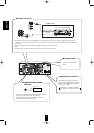
Notes:
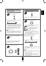
• The phono input of your receiver is not suitable for the direct connection of a turntable with a Moving Coil (MC) cartridge. If you have
a MC cartridge, use a separate head amplifier of step-up transformer between the turntable and the receiver.
• Not all of the commercially available Fiber Optic cables are suitable for use with this receiver. If you have a question as to the
suitability of any cable, please check with your dealer or a qualified service organization.
• Remove the protective cap before making any OPTICAL connections. Re-insert the protective cap when not using the OPTICAL jacks.
OPTICAL OUT
PLAY(LINE OUT)
REC(LINE IN)
OPTICAL OUT
OPTICAL IN
CD player
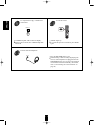
POWER
REMOTE SENSOR
PROGRAM/REVIEW
RANDOMREPEAT
OPEN/CLOSE
PHONES LEVEL
PHONES
MIN MAX
ON/OFF
MULTIPLE COMPACT DISC PLAYER CDC-5080R
12345
GRAPHICSPEAKDELETEEDIT
SCENETRACK
INDEXSTEP
AB
V-CD PBCREVERTPROGAUTO RANDOMREPEATALL1DISCS
123
456
789
101112
131415
MPXINTROA< >B
Tumtable with MM type cartridge
■ CONNECTING AUDIO COMPONENTS
GND
Additional
audio component
Additional MD recorder
for digital recording
Tape deck or
MD recorder
TAPE
MON.
OUT
L R
REC
PHONO
CD
AUX
IN
TAPE
MON.
TAPE/MD
CD
OUT
OPTICAL
“
is a trademark
of SRS Labs,
Inc.”
ENGLISH