


2
Table of Contents
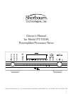
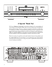
4 Thank You for your PT-7010A Purchase
5 Safety Precautions
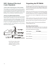
6 NEC (National Electrical Code) Standards
6 Note for Cable Television (CATV) Installer
6 Antenna Grounding Outside the House
6 Unpacking the PT-7010A
6 Recording the Serial Number
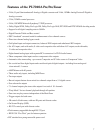
7 Features of the PT-7010A A/V Controller
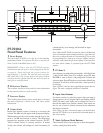
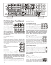
8 PT-7010A Front Panel Features
8 Power Button
8 IR Receiver Window
8 Processor Display
8 Z2 (Zone 2)
8 Input Select Buttons
8 MODE UP/DOWN (Mode Buttons)
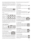
9 AM/FM Tuner Controls
9 Tone Controls
9 Signal Processing Indicator Lights
9 MUTE Button
9 PANEL DIM Button
9 Additional Front Panel Lights
9 COM/RECV
9 ZONE TWO POWER
9 ZONE TWO ADJUST
9 SIDE AXIS
10 PT-7010A Rear Panel Layout
10 Audio/Video Inputs
10 Audio/Video Outputs
10 Component Video In
10 Component Video Out
10 Infrared (IR) Inputs
10 Triggers and Relay
11 RS-232Port
11 XLR Audio Outputs
11 Main Audio Outputs
11 8-CH Analog Input
11 FM Antenna
11 AM Antenna
11 Ground Screw
11 Audio Inputs
11 Audio Outputs
11 Stereo Outputs
11 Side-Axis Outputs
12 IEC Line Cord Socket
12 Digital Inputs
12 Digital Output
12 IEEE-1394"Firewire”Port
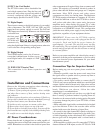
12 Installation and Connections
12 AC Power Considerations
12 Connection Tips for Superior Sound
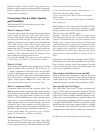
13 Connection Tips for Video Quality and Flexibility
13 What is Composite Video?
13 What is S-Video?
13 What is Component Video?
13 Video Up Conversion
13 Video Output to the Main Screen and OSD
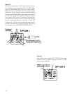
13 Zone Specific Turn-On Triggers
14 Trigger connection Option 1 and 2
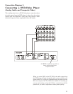
15 Connection Diagrams
15 Connecting a DVD-Video Player (Analog Audio
and Composite Video)
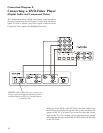
16 Connecting a DVD-Video Player (Digital Audio
and Component Video)
17 Connecting to the TV or Projector using
Component Video
18 Connecting a VCR (Analog Audio and Composite
Video)
19 Connecting a CD Player (Analog Audio)
20 Connecting a Cassette Tape or DAT Deck
21 Connecting the 8-Channel Analog Inputs
22 Connecting the AM and FM Antennas
23 Connecting an Amplifier (MAIN ZONE)
24 Connecting an Amplifier (ZONE 2)
25 Connecting an Amplifier (ZONE 2)
26 Overview of the PT-7010A Remote
26 Button Layout
26 LCD Display
26 Button and Display Light
26 DEVICE Buttons
26 PAGE Button
27 MAIN Button
27 FAV Button
27 JOYSTICK PAD
27 M1, M2 and M3 Macro Buttons
27 Quick Start Setup Instructions
27 Adding Batteries to the Remote Control
27 Quick Start Instructions for PT-7010A Setup
30 Operation of the PT-7010A using the Remote
30 Turning on the MAIN Zone
30 Turning on ZONE 2
31 Programming and Configuring YOUR
Components
31 P-PRO
31 LEARN
32 EDIT
32 FAV
32 PUNCH
33 ERASE
33 LIGHT
33 MACRO
33 RECAL (Recall)
33 CLONE
34 The On-Screen Display (OSD) Functions
34 Video Connections
34 OSD Activation
34 Quick Access to Information