


– 40 –
MD-MT877/MD-MT877C
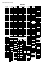
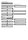
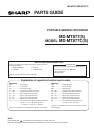
• Recording/playback operation.
Yes
Does the head move down, failing to start record even
when the continuous record mode is set after address ?
No
Does level of pins 43 of IC401 and pin 86 of change
depending on record and playback ?
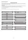
Is RF pattern output from IC201 pin 50 ?
Yes
No
Check for soldering failure of IC201 .
No
Check periphery of IC401 and IC101.
Check whether there is any damage in IC101, periphery of
laser diode.
Yes
Check for defects of IC351 in head drive flexible PWB,
head, flexible PWB.
No
No
Check the periphery of IC501 and the waveform of the pins
70 to 73 of IC201.
No
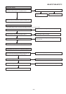
Check whether the voltage of pins 13 to 15 of IC701 varies with
the recording VOLUME +/– button operation. Check whether the
soldering of IC701 is poor.
No
Check whether the audio signal line between IC701 and J701 is
defective.
Is audio waveform observed on the pins 10 and 12 of IC701 ?
Yes
Check whether input waveform is observed on the pins 5
and 6 of IC701.
Yes
Check voltage of pins 57 and 58 of IC201, pins 2, 3, 6, and 7 of
IC651, pins 4 and 5 of CN601. Check whether disc is record-
inhibited.
Does the RF waveform appear at TP201 when recording/
Playback is performed.
Check whether the pin 7 of IC501 and the pin 81 of IC201 are in
H state.
Yes
Yes
Is the output waveform output to the pin 8 of IC501 ?
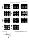
Change MSL from 00H to 80H by the control setting of EEPROM. After completing the operation, return in to 00H.
Insert a low reflection disc, and ascertain audio output by normal playback, and then set TEST REC mode.