


– 10 –
MD-MT877/MD-MT877C
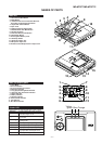
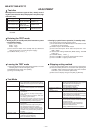
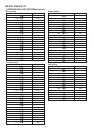
1 Bottom Cabinet 1. Screw .....................(A1) x5 10-1
2 Top Cabinet 1. Open the Top cabinet.
10-1
2. Screw ..................... (B1) x4
3. Flexible PWB.......... (B2) x1 10-2
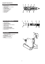
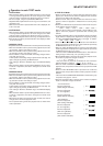
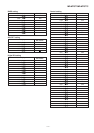
3 Main PWB 1. Open the rechargeable
10-2
battery compartment of the
direction indicated by arrows.
2. Screw .................... (C1) x1
3. Flexible PWB......... (C2) x2
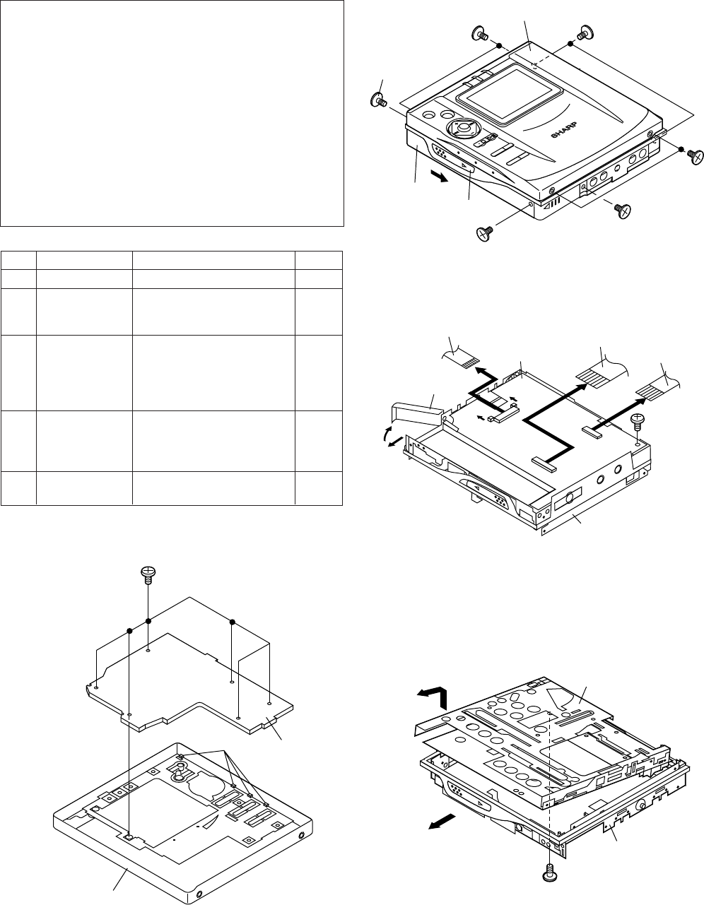
4 MD Mechanism 1. Pull the main frame to the A 10-3
direction and remove the MD
mechanism upward.
2. Screw .................... (D1) x1
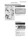
5 LCD PWB 1.
Screw
...................... (E1) x6 10-4
2.
Hook .......................
(E2) x4
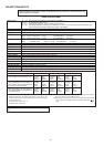
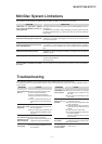
DISASSEMBLY
Cares before disassembling
When assembling the machine after disassembling or
repair, observe the following requirements so as to ensure
safety and performance.
1. Remove the batteries from the machine, and take out the
mini-disc.
2. When assembling after repair, be sure to position the
wires in the same location.
Use the specified screws to fix the cabinet and the
mechanism unit. The use of the screws with length other
than specified may cause contact with the mechanism
unit resulting in malfunction.
3. When repairing, pay close attention so not to damage the
IC from static electricity.
REMOVAL
PROCEDURE
STEP
FIGURE
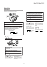
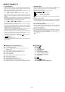
Figure 10-1
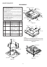
Figure 10-2
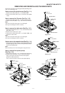
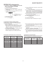
Figure 10-4
Caution:
Carefully handle the main PWB and flexible PWB. After removing the
flexible PWB (1*) for the optical pickup from the connector, do not
touch directly the front end of flexible PWB with your hand so as to
prevent damage of optical pickup by static electricity.
Figure 10-3
OPENOPEN
OPEN
Top Cabinet
Bottom Cabinet
EJECT
Knob
(B1) x 2
ø 1.4 x 2 mm
(B1) x 2
ø 1.4 x 2 mm
(A1) x 1
ø 1.4 x 2 mm
(A1) x 1
ø 1.4 x 2 mm
(A1) x 1
ø 1.4 x 2 mm
(A1) x 2
ø 1.4 x 2 mm
OPEN
(C1) x 1
ø 1.4 x 2.5 mm
(C2) x 1(1*)
(C2) x 1
(B2) x 1
pull
pull
Battery
Cover
Main Frame
Main PWB
1
2
OPEN
A
Main Frame
MD Mechanism
OPEN
(D1) x 1
ø 1.4 x 1.5 mm
(E1) x 6
ø 1.4 x 2 mm
(E2) x 4
LCD PWB
Top Cabinet