


MD-MT877/MD-MT877C
– 15 –
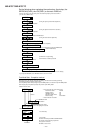
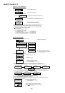
EEPROM (IC402) writing procedure
1. Procedure to replace EEPROM and write initial
value of microcomputer in EEPROM
(1) Replace EEPROM.
(2) Refer to the latest EEPROM data list.
(3) Start the test mode. (Refer to page 12 "Entering the
TEST mode".)
(4) Version display (At the time of settlement of the test
mode by the button operation.)
[ V e r . ]
EEPROM version (c ~ z)
Microcomputer ROM
version
(5) The whole LCD lights.
(6) Test mode stop state.
[ T E S T ]
Ambient
temperature
Temperature
correction
+ 8
o
C ~ +10
o
C - 05h + 9.1
o
C
+11
o
C ~ +13
o
C - 04h + 12.0
o
C
+14
o
C ~ +16
o
C - 03h + 14.9
o
C
+17
o
C ~ +19
o
C - 02h + 17.8
o
C
+20
o
C ~ +22
o
C - 01h + 20.7
o
C
+23
o
C ~ +25
o
C ± 00h + 23.6
o
C
+26
o
C ~ +28
o
C + 01h + 26.9
o
C
+29
o
C ~ +30
o
C + 02h + 29.4
o
C
+31
o
C ~ +33
o
C + 03h + 32.3
o
C
Center
temperature
Ambient
temperature
Temperature
correction
Center
temperature
- 9
o
C ~ +10
o
C 08h + 0.5
o
C
+ 3
o
C ~ +21
o
C 07h + 12.0
o
C
+15
o
C ~ +33
o
C 06h + 23.6
o
C
+26
o
C ~ +43
o
C 05h + 35.0
o
C
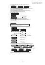
(7) Press the "BASS" button, and press 1 time the "FAST
REVERSE" button.
[ E E P R O M ]
(8) Perform the operation to display "EEPROM SETTING
MODE CHART", compare the EEPROM DATA LIST
with the display, and set according to the EEPROM
DATA LIST with the VOLUME+ or VOLUME– button.
(9) Set the temperature reference. (Refer to the Tempera-
ture reference setting method.)
(10) Set according to the EEPROM DATA LIST.
(11) Press the STOP button.
[ T E S T ]
(12) Press the STOP button.
(13) After data is written in EEPROM, turn off power .
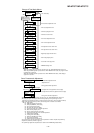
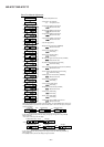
2. Temperature reference setting method
[1] Measurement, calculation and setting procedure
(1) Set the TEST mode.
(2) Start the EEPROM mode 'Temp' menu.
• Button operation in order of BASS, FAST REVERSE x
1 time, PLAY, PLAY in the test mode STOP state.
• 'TM$$%%' is displayed. ($$= Temperature code, %%
= Temperature reference)
(3) Once press FAST FORWARD, and determine the dis-
played microcomputer TEMP input AD value.
• 'TPin##' is displayed. (## = TEMP input AD value)
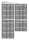
(4) At the ambient temperature, determine the tempera-
ture corrected value from the temperature measure-
ment value correction table.
(5) Determine the temperature reference, using the follow-
ing formula.
• Temperature reference = Microcomputer TEMP input
AD value + Temperature corrected value.
(6) Set the temperature reference value by button opera-
tion, and check whether the temperature code indica-
tion corresponds to "Temperature Code Identification
Table".
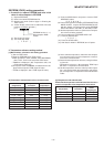
[2] Temperature measurement value correction table
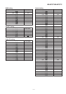
[3] Temperature code identification
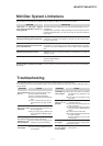
Check that the temperature code indicated after the servo
control corresponds to the temperature limits below