3
ENGLISH
3
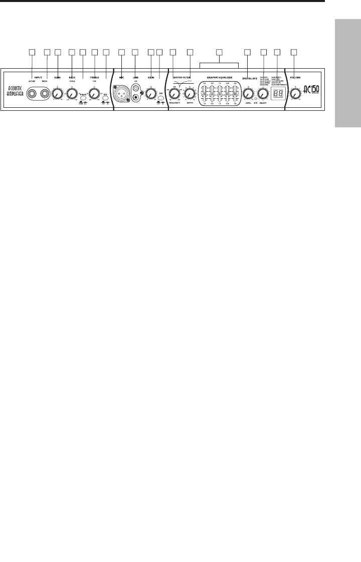
Guided Tour - Front Panel
AC75 and AC150 Front Panel
1. ACTIVE Input - 1/4-inch phone jack for connecting active inputs. Use this input if your gui-
tar pick-up uses a battery.
2. PIEZO (Passive) Input
- 1/4-inch phone jack for connecting passive inputs. Use this input if
your guitar pick-up does not use a battery.
3. GAIN (Channel 1
) - Control knob is used to control the overall level of the Channel 1 input.
4. BASS -
Controls the amount of bass, or low frequency, applied to the input connected to
channel 1.
5. PHASE -
Used to reverse the input signal polarity.
6. TREBLE -
Controls the amount of treble, or high frequency, applied to the input connected
to channel 1.
7. EFX (Channel 1) -
Used to add effects to the signal connected to the Channel 1 input.
8. MIC Input
- XLR input connector for connecting to Channel 1’s low-noise Microphone Pre-
amp, with Phantom power available for condenser microphones.
9. LINE Input
- RCA inputs for connecting an external line level signal like that from a CD, MP3
player or sound card.
10. GAIN (Channel 2
) - Control knob is used to control the overall level of the Channel 2 input.
11. EFX (Channel 2) -
Used to add effects to the signal connected to the Channel 2 input.
12. FREQUENCY (Notch Filter) -
Used to set the center frequency for the Notch Filter.
13. DEPTH (Notch Filter) -
Control Knob used to control the amount of attenuation applied by
the Notch Filter.
14. GRAPHIC EQUALIZER
– These sliders allow you to “draw” the tonal response of the system
by adding 12 dB of boost or attenuation to seven different narrow-band frequency areas
(100Hz, 315Hz, 1kHz, 3.5kHz and 10kHz.) affecting the main output signal of the AC75 or
AC150. When a slider is at its center detented (“0”) position, the selected frequency area is
unaffected (it is said to be flat). When a slider is moved up (above the “0” position, towards
the “+12” position), the selected frequency area is boosted, and when it is moved down
(below the “0” position, towards the “-12” position), the selected frequency area is attenuated.
For more information, see the “About Equalization” section on pages 13 - 14 of this manual.
15. EFX LEVEL –
Control knob used to set the amount of digital effect that’s mixed in with the
channel input signals.
16. EXF SELECT -
Used to select one of the available 100 digital effects presets.
17. EFX PRESET Display -
Shows the current selected preset program number.
18. VOLUME
- Control knob used to control the overall level of the AC75 or AC150 amplifier.


