


5
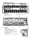
INTRODUCTION- Illustrations
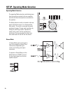
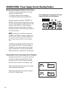
FRONT PANEL
1- Power switch 4- Gain controls
2- Power, Standby, and Protect LEDs 5- Signal, -20 dB, -10 dB, and Clip LEDs
3- Cooling air exhaust vents
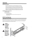
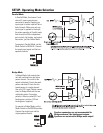
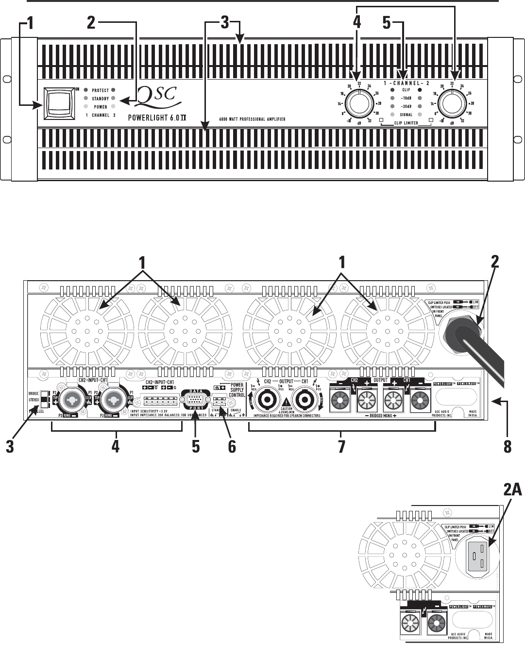
REAR PANEL
1- Cooling air inlet vents
2- Domestic (North America) fixed AC power cord entry
2A- Export IEC-style detachable power cord entry
3- Mode switch (Bridge/Stereo/Parallel)
4- Input connectors (“combo” XLR/TRS and terminal blocks)
5- QSC DataPort Connector (interfaces with QSC accessories)
6- Remote power supply control
7- Output connectors
8- Operating voltage and serial number tag location (side of unit)