


25
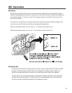
APPENDIX-
DataPort Pinout
The DataPort connection is QSC-specific. Informa-
tion is subject to change.
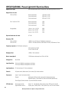
SPECIFICATIONS- PowerLight 6.0 II Electrical Data
QSControl Control and Monitor Parameters on/standby, channel gain, mute, polarity, input level, output level, heat sink
temperature, output load sense, clip detect, protect detect, operating Mode
sense (Stereo/Parallel/Bridge)
Cooling four continuously variable speed fans, rear to front airflow
Amplifier Protection short circuit, open circuit, thermal, ultrasonic, and RF protection
stable into reactive or mismatched loads
Load Protection turn-on and turn-off muting, DC fault power supply shut down
Weight 53 lbs (net), 60 lbs (shipping)
Power Requirements 120 Volts AC, 50 to 60 Hertz, 30 Amp NEMA L5-30 receptacle
OR
240 Volts AC, 50 to 60 Hertz, 15 Amp service
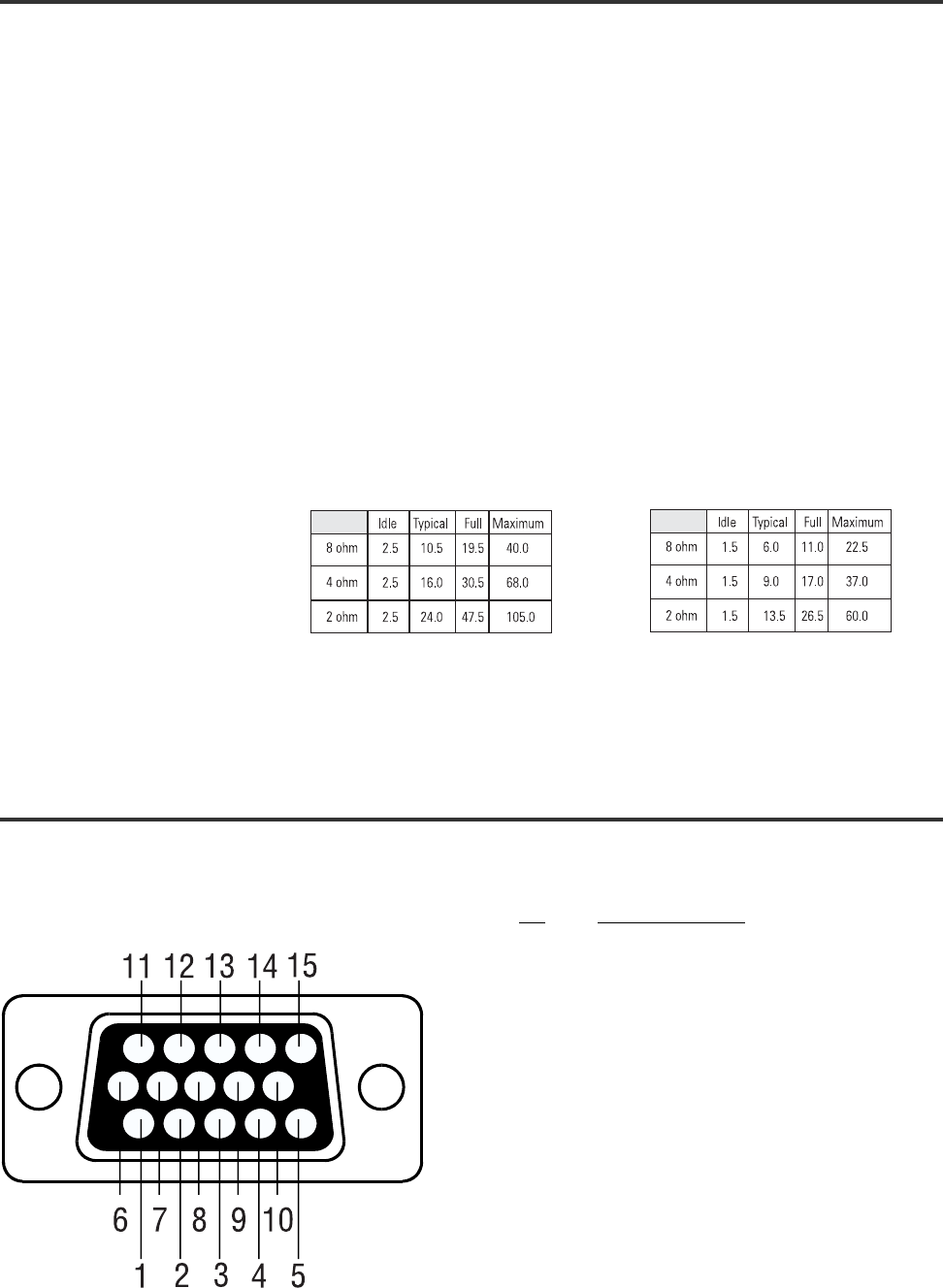
Current Consumption
(in amperes, rms)
Current Consumption Notes: Typical- 1/8 power, pink noise, represents typical program with occasional clipping
Full- 1/3 power, pink noise, represents severe program with heavy clipping
Maximum- continuous sine wave at 1% clipping
Note: Specifications are subject to change without notice.
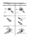
Pin Signal Description
1 Ch. 1 Minus (-) Input Signal
2 AC Standby Control
3 V- MON Ch. 1 and Subcode 1
4 I- MON Ch. 1 and Subcode 2
5 Clip/Protect Ch. 1
6 Hard Ground
7 Ch. 1 Plus (+) Input Signal
8 Ch. 2 Plus (+) Input Signal
9 +15V from Amplifier
10 Data Reference Ground
11 Ch. 2 Minus (-) Input Signal
12 Amplifier IDR (Model ID)
13 V- MON Ch. 2 and Subcode 3
14 I- MON Ch. 2 and Subcode 4
15 Clip/Protect Ch. 2
120 Volts
240 Volts