


16
CONNECTIONS- Power Supply Control (Standby/Enable)
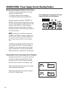
Remotely Controlling the Amplifier’s Power Status
Power Supply Control 2-pin connector is located
between the DataPort and CH2’s Speakon.
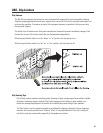
Using the Rear Panel Power Supply Control Connector
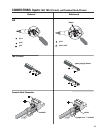
Included with the PL6.0 II is a 2-pin terminal block
connector for the Power Supply Control. Using
two wires, a S.P.S.T. switch, and the connector,
wire the control as shown in the diagram, right.
When the switch contacts are open, the amplifier
will be operating normally (on).
When the switch contacts are closed, the ampli-
fier will be in Standby mode.
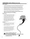
The PL6.0 II provides two methods for remotely
controlling its Power Status:
1- the Power Supply Control connection
2- the DataPort connection (using QSControl)
Two status modes are possible: STANDBY and
ENABLE. Using the Power Supply Control connec-
tion, all that is required is a switch and some two-
conductor cable. Below is a hookup diagram
outlining the required connections. If using the
DataPort connection, refer to QSControl’s help file
for more information.
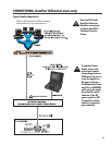
NOTE! In order for the amplifier to respond to
STANDBY and ENABLE commands, whether from
the rear-panel connector or DataPort/QSControl,
the AC Power Switch MUST be in the ON posi-
tion.
If remotely controlling the AC Power Status, turn
the AC Power Switch ON. Place the amplifier in
STANDBY by using the rear-panel Power Supply
Control connections or by using the appropriate
QSControl software, connections, and commands.