


7
2.39 Operation and Indicators Note that the Gain controls are calibrated in dB. As you turn the Gain down, it takes
more input signal to reach full power, so the Gain should be kept in the upper 12 dB of its range for full power output
from normal signal sources. The “0 dB” reference indicates that the amplifier gain is at 26 dB when the knob is
adjusted to this position.
Note that full amplifier output power may be achieved even if the gain controls are not turned fully up. However,
a larger input signal will be required to produce full rated output.
LED (Light Emitting Diode) indicators monitor the operation of the amplifier. A green LED serves as the pilot light
to indicate that power is on. Each channel has a red “Clip” indicator that will show any distortion in the amplifier.
Upon power up, these may not flash symmetrically. This does not necessarily indicate that there may be a problem.
The muting circuit blocks the sound for three seconds after turn-on and immediately after turn-off. This prevents
turn-on and turn-off thumps and transients from reaching the speakers.
Please refer to Section 3 for more detailed instructions.
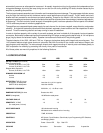
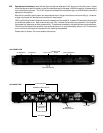
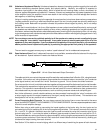
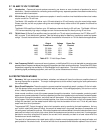
1100 FRONT VIEW
AC BREAKER
AC SWITCH
GAIN CONTROLS
HEADPHONE
JACKS
PILOT LIGHT
CLIP INDICATORS
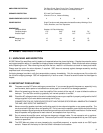
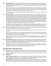
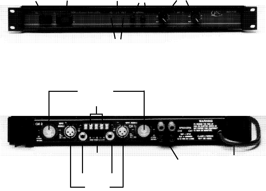
1100 BACK VIEW
AC CORD
BARRIER STRIP INPUTS
1/4 INCH INPUTS
INPUT
PROGRAMMING
SWITCHES
OCTAL SOCKET
XLR INPUT
SPEAKER
BINDING POSTS