


18
that stage. Assuming that the hiss has not always been there, this indicates defective electronics. Certain special-
effects units are rather noisy, so compare with other users.
Crackles—defined as a “popcorn” noise. If the crackle persists during pauses in the program material, this
indicates defective electronics and must be traced down using the above procedures. Crackles which occur during
audio peaks or when the electronics are vibrated usually indicate bad connections.
IV: SPEAKER PROTECTION
4.1 BACKGROUND
Speakers have several limits which should not be exceeded for reliable operation. It is the user’s responsibility
to determine these limits and operate the amplifier accordingly. We offer several ways to avoid unexpected
accidents, but you must still select speakers of appropriate type and power capacity and operate them within their
limits.
4.2 DC PROTECTION
The design of the 1100, 1200 and 1400 amplifier circuit eliminates the DC fault problem at its source, so no special
protection is required. The QSC grounded collector output circuit is AC coupled and cannot pass DC to the load.
The Model 1700 features a Load Grounding™ relay and special protective circuitry to protect the load from any
DC fault condition.
All Series One amplifiers feature a low frequency roll-off below 20 Hz to protect the amp and load from possible
damage caused by large subsonic transients, such as breath pops, dropped microphones, etc.
4.3 HORN DRIVER PROTECTION
The compression drivers used with horns for high-frequency reproduction have special protection requirements.
These devices are more delicate than large cone speakers, and more vulnerable to overload damage. In
particular, the driver has a low-frequency limit which must be carefully observed. Below this frequency, the driver
diaphragm can “bottom out” which will immediately alter the frequency response, and quickly cause failure. To
prevent this, the user must make sure that a proper crossover network is installed.
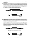
In bi-and-tri-amp systems, where the driver is connected directly to the amplifier, the user must be especially
certain that the correct frequency is used on the electronic crossover, and that no low-frequency signals, such as
loud hums, get into the signal path between the electronic crossover and the power amplifier. As further protection,
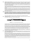
especially against accidental mis-adjustment or bad cables, many users install “horn protection capacitors” wired
in series between the amp and driver. This part inherently blocks lower frequencies and DC, but must be selected
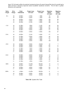
so as not to disturb the crossover frequency. A reasonable rule of thumb is to let the capacitor roll off one octave
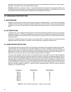
below the intended crossover frequency. A table of values is presented below. Be sure to use non-polarized
capacitors, of at least 50V rating.
Frequency 8-ohm Driver 16-ohm Driver
500 Hz 80 40
800 Hz 50 25
1000 Hz 40 20
1200 Hz 33 16
2000 Hz 20 10
3500 Hz 12 6
7000 Hz 6 3
Table 4.3 Horn Protection Capacitors. (Values in micro farads)