


4
automatically as soon as safe operation is assured. An equally important muting circuit protects the loudspeakers from
unexpected damage, by muting the amp during turn-on and turn-off and by blocking DC faults, whether caused by the
amplifier or preceding components.
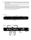
The front panel presents essential user information and is recessed to prevent damage. The green power indicator serves
as a pilot light and individual red clip indicators monitor overall performance of each channel. The AC switch and circuit
breaker are front mounted for convenience and quick resetting. Except for the Model 1100, the Gain controls and input
programming switches have been placed on the back of the amplifier to protect them from damage, inadvertent adjustment,
or tampering. The Gain controls, as well as a pair of headphone jacks, have been placed on the front panel of the Model
1100 to allow easy access in monitoring applications.
The amplifiers use a separate bipolar power supply for each channel, for minimum crosstalk, cross-distortion, and greater
reliability. A single dual-secondary transformer feeds isolated, separately fused rectifiers and filter capacitors for each
channel. Thus the remaining channel can keep running in case of breakdown.
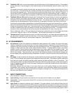
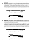
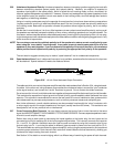
In order to interface properly with a variety of pro-audio systems, we have included all of the popular input and speaker
connectors. Balanced or unbalanced inputs can be made using XLR plugs, screw lugs to the barrier strip, or 1/4-inch phone
plugs (ring-tip-sleeve for balanced inputs). Speaker connections are made with 5-way binding posts.
The steel chassis, of the 1200, 1400 and 1700, is a 14 gauge, single piece design with integral rack mounting ears. The
1100 chassis features single piece aluminum extrusions that form the sides of the chassis and feature integral rack
mounting ears and heatsinks. The extra strength chassis and rugged mounting of internal parts contributes greatly to
QSC’s reputation for reliability by protecting the circuitry from years of road abuse.
All of these points are more fully explained in the following Sections.
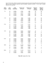
1.4 SPECIFICATIONS
1100 1200 1400 1700
OUTPUT POWER (per channel)
Both Channels Driven
8 ohms, 20-20 kHz, 0.1% THD 50w 100w 200w 325w
4 ohms, 20-20 kHz, 0.1% THD 70w 150w 300w 500w
Bridged-Mono Operation
8 ohms, 20-20 kHz, 0.1% THD 140w 300w 600w 1000w
DYNAMIC HEADROOM dB
8 ohms 2.0 2.0 2.0 1.9
4 ohms 2.3 2.5 2.5 2.9
DISTORTION, THD @ 8 ohms
20-20 kHz, at rated power Less than 0.1%, 0.01% typical
SMPTE-IM at rated power Less than 0.025%
FREQUENCY RESPONSE 20-20 kHz, +0, -1.0 dB at 1 watt
DAMPING FACTOR @ 8 ohms Greater than 200
NOISE (A-weighted) 100 dB below rated power
VOLTAGE GAIN, dB 26 29 32 34
SENSITIVITY, V RMS 1.0 1.0 1.0 1.0
(for rated power, 8-ohms)
INPUT IMPEDANCE 10K unbalanced inverting
20K balanced or unbalanced non inverting
CROSSTALK -70dB, 20-20 kHz
CONTROLS AC Switch, Circuit Breaker, Gain Knobs, Input Programming DIP Switches,
and Bridging Switch
INDICATORS Power: Green LED Clip: Red LED
COOLING Convection Convection 2 speed fan 2 speed fan