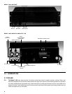
12
3.38 Good Quality Connections A tight and corrosion-free contact at all connections is essential for good sound and
to avoid erratic noises or unstable performance. 1/4-inch connectors are suitable for low-cost portable systems,
but must be removed and replaced frequently to avoid corrosion build-up. 1/4-inch plugs are not recommended
for long, undisturbed service, especially in corrosive environments. The “military” brass-type plugs are especially
bad in this respect, because they don’t match the plating of the input jacks. XLR plugs are preferred by professional
users for reliable contact and better retention.
For permanent wiring harnesses, the barrier strip is the cheapest and best. The signal wiring can be stripped and
wrapped around the terminal screws, or spade terminals can be soldered or crimped onto the ends of the signal
conductors. When crimping, be sure to use the proper tool with generous pressure, and test the resultant crimp
by pulling while closely inspecting. If the wire wiggles inside the crimped terminal, the contact will go bad. The
spade lug, or bare wire ends, can then be tightly screwed down to the proper positions on the barrier strip. If high
pressure is maintained in the crimp and the screw terminal, a “gas-tight” connection is formed which will exclude
corrosion for many years.
3.4 OCTAL MODULE ACCESSORIES
3.41 Octal Socket Each channel has an octal socket for active and passive plug-in accessories. This is shipped with
a protective label to prevent corrosion of the pins. See the schematic in the back of this manual for pin assignments.
3.42 Input Transformer Although the audio benefits of transformerless coupling are well recognized, certain users
still prefer the security of a transformer-coupled input in severe environments. In addition to the QSC model T-1
input transformer, the Bauer Communication model RE-11P-QN is available for QSC amplifiers.
3.43 Active Accessories In a number of special cases, the user needs built-in power limiting, bi-amp capability, etc.
In order to serve these needs without adding to the basic cost of the amplifier, the octal socket has been designed
with low-level DC power tapped off the internal supply of the amplifier. Ask the QSC Sales Department for details
on availability.
3.44 Octal Module Installation Peel away the protective cover and plug in the module, observing correct alignment
of the guide post in the middle. The input bypass switches for that channel must be turned off (See Section 3.5).
Certain other switches may need to be set in accordance with the type of module and combination of channels
desired. See the instruction sheet for each module for these details. Input to the module occurs automatically
through the amplifier’s input jacks.
3.5 INPUT SWITCHES AND MONO BRIDGING
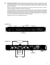
3.51 Input Programming Switch An 8-pole input programming DIP switch will be found on the rear panel of the
amplifier. The switch functions are as follows: (move levers up to turn on, down for off)
Switches 1,2: Bypass the Octal Socket for Channel 2. Keep “on” for normal operation (i.e. when no octal accessory
in used). Turn “off” when an octal accessory is plugged in (see the instructions with the octal accessory).
Switches 7,8: Same as above for Channel 1.
Switches 3,4: Connects the output from an octal accessory plugged into Channel 1 to both amplifier channels.
Turn “on” to feed the octal accessory to both channels. Turn “off” for normal operation or for using separate octal
accessories.
Switches 5,6: Connects the inputs of Ch. 1 and Ch. 2 in parallel (see Section 3.37). If octal accessories are used,
the inputs (not the outputs) of both accessories will be combined. This may be used in place of a Y-cord for feeding
a common input signal to both channels.
3.52 Mono Bridging Most stereo amplifiers have a method of combining both channels in series to give the combined
power into a single load. This is a way to fully use both channels when only a single speaker is driven.
To engage the bridged-mono mode of the Model 1100, a slide switch must be set through a hole in the bottom
of the amplifier. Due to the danger of touching live terminals inside the amplifier, BE SURE TO REMOVE ALL
POWER AND DISCONNECT THE AC PLUG before resetting the switch. In accordance with the label on the
bottom, set the switch towards the front for bridged-mono use, and towards the rear for normal stereo use.
To engage the bridged mono mode on the Model 1200, 1400, or 1700, there is a separate slide switch located
below the barrier strip inputs on the rear panel. Follow the directions on the label to engage the switch in the
“Bridge” position.


