


11
3.36 Unbalanced Inputs and Polarity Unbalanced operation raises an interesting question regarding the trade-offs
between maintaining standard system polarity and optimal stability. Normally, an amplifier is expected to
reproduce input signals in the same polarity, which is called the non-inverting mode, so that a drum beat, for
instance, pushes the speaker out instead of in. However, if there is any leakage from high-power (speaker) circuits
to the amplifier inputs, the amplifier is much more stable in the inverting mode, since the leakage then tends to
add negative, or stabilizing, feedback.
Using an inverting-mode power amp is the opposite of normal practice, but we have observed many cases where
“mystery problems” occurring in wide-band amplifiers used in the non-inverting mode are solved by switching to
the inverting mode. Balanced line operation corrects this problem without regard to polarity, but is not always
available.
We feel that in most situations, it is of very little importance to worry about overall amplifier polarity, as long as all
the speakers are matched, because the polarity of mics, mixers, recordings, speakers, etc. may be unknown. For
this reason, we have used the safest or most stable assignment (inverting) for the input polarity of the 1/4-inch plug,
to give average users with unbalanced equipment the most stable connection without getting bogged down in very
subtle nuances of reproduction.
NOTE
You can always reverse the red-black polarity to all the speakers to restore correct overall polarity even
when using the “more stable” inverting mode. In any case, be sure to use the same polarity for all of the
speakers so they work together. If you can determine the polarity of the rest of the chain, you can always
obtain positive overall reproduction polarity, by selecting the appropriate final polarity to the speakers.
The next section suggests an easy way to make a “quasi-balanced” line for unbalanced components.
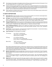
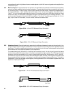
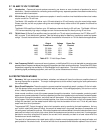
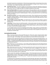
3.36 Quasi-balanced lines Even if a balanced-line output is not available, some benefits of a balanced-line input can
still be obtained. Special cables will need to be made as follows:
Amp Input
Figure 3.36 1/4-inch Quasi-balanced Output Connection
The cable end which connects to the power amplifier would be made as described in Section 3.34, using balanced-
line cable. At the other end, using whatever plug matches the unbalanced output, connect the “plus” conductor
to the signal terminal, and connect the “minus” conductor to ground. Do not connect the shield conductor.
Do not connect the “minus” and shield conductors together at the power amplifier (balanced input) end of the cable.
This maintains the separation of signal ground and shield (circuit) ground needed to obtain balanced-line noise
rejection. This scheme is recommended to remove the last traces of hum and interference from systems which
use unbalanced-line pre-amps and processors, such as ordinary consumer stereo and audiophile gear.
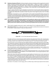
As a further refinement, a small variable resistance can be connected in series with the “minus” conductor, with
a value roughly equal to the output impedance of the signal (usually less than 600 ohms). This resistance can
be adjusted to null out any residual hum or interference.
3.37 Cross Connecting Both Channels You can always connect the inputs of two or more channels to the same
signal, but NEVER CONNECT TWO CHANNELS TO THE SAME SPEAKER. Connect separate speakers to each
channel to avoid amplifier damage.
Rather than using a patch cable or connecting the inputs together at the barrier strip, the two inputs can be
connected by turning on switches 5,6 of the input programming switches. This internally connects the inputs for
Ch. 1 and Ch. 2 in parallel. Additional amps can now be cross-connected by using the connector style of your
choice to plug into Ch. 1, and using the same (or different) type connector to come out of an input jack for Ch. 2.
This second cable can now be connected to a second amplifier, and by using the same procedure, can be patched
to as many amps as desired. Each channel’s Gain control will remain effective for that channel only, allowing you
to balance the output coming from each channel.
See Section 3.5 for details on mono-bridging, which is a different way of combining the power of both channels.