


10
mismatches will result in slight loss of common-mode rejection, but will still have much greater noise rejection than
unbalanced inputs.
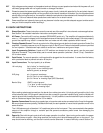
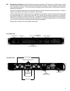
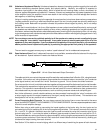
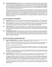
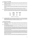
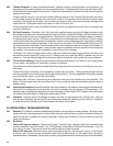
3.34 Balanced Inputs For proper balanced-line operation, the cable shield should be connected at the power amplifier
end only and kept separate from both signal conductors. The cable shield should be connected to the barrel of
a 1/4-inch plug, to pin 1 of an XLR plug, or to the “GND” terminal of the barrier strip. Balanced-line cables contain
two signal conductors, a “plus” polarity, often called “high” or “hot”, and a “minus” polarity, often called “low” or
“return”. The “plus” conductor should go to the ring of a 1/4-inch plug, to pin 2 of an XLR plug or to the “plus” input
of the barrier strip, for the amplifier to reproduce the signal in the same polarity (non-inverting operation). This
conforms to the international standard for XLR connections. The “minus” conductor goes to the tip of a 1/4-inch
plug, to pin 3 of an XLR connector, or to the “minus” terminal of the barrier strip.
Amp Input
Figure 3.34a 1/4-inch RTS Balanced Output Connection
1
2
12
3
3
Amp Input
Figure 3.34b 3-Pin XLR Balanced Output Connection
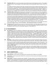
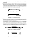
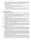
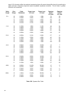
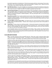
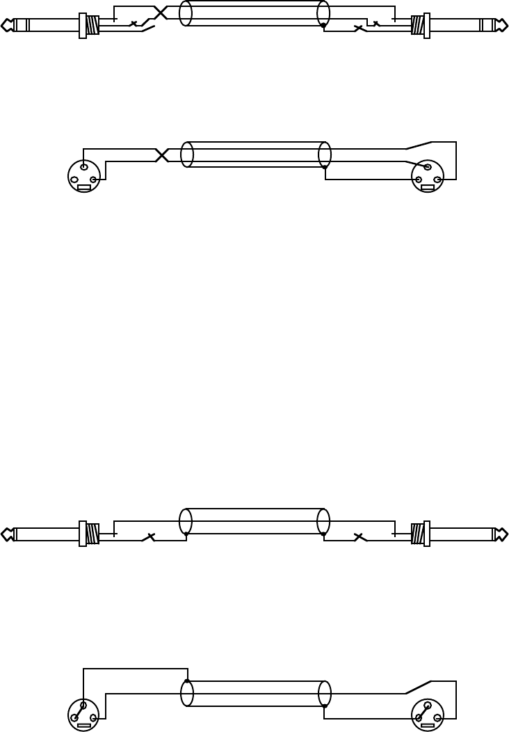
3.35 Unbalanced inputs Since the input signal responds to the difference between the plus and minus signals, if only
a single-ended, unbalanced signal is available, the unused input terminal must be grounded for operation without
loss of gain. The ability to reject cable-induced hum and noise is lost, but this may not be needed in well-shielded
environments with short distances between audio components.
For unbalanced signals, the barrel of an ordinary two-conductor (mono) 1/4-inch plug will ground the sleeve
terminal when pushed all the way into the 1/4-inch jack, so no special wiring is required. For XLR plugs, the signal
conductor should be connected to pin 2, and pin three should be connected, inside the plug , to pin 1 (ground).
On the barrier strip, the “minus” terminal is tied to the adjacent “GND” terminal, and the signal conductor should
be connected to the “plus” terminal. In all cases, of course, the shield goes to the ground terminals. The tip of an
unbalanced 1/4-inch plug has been made negative (inverting) because it is far more stable in systems which are
subject to complex ground loops.
Amp Input
Figure 3.35a 1/4-inch RTS Unbalanced Output Connection
1
2
12
3
3
Amp Input
Figure 3.35b 3-Pin XLR Unbalanced Output Connection