


6
2.27 High voltages can be present on the speaker terminals. Always connect speaker terminals with the power off, and
use heavy gauge cable with no frayed strands or damaged insulation.
2.28 Please be aware that power amplifiers have high power circuitry inside with potential for fire and shock hazard;
never plug in a damaged amplifier until the condition of the internal insulation is checked. If a circuit breaker blows
quickly when turning the amp on, the amplifier is defective and should not be restarted until the amplifier has been
repaired. Failure to observe these precautions could lead to fire or shock hazard.
2.29 Power amplifiers are inherently heavy and may become hot after use; provide adequate support and be careful
how you hold the amplifier when handling it.
2.3 QUICK INSTRUCTIONS
2.31 Stereo Operation These instructions cover the normal use of the amplifier in two-channel or stereo applications.
See Section 3 for detailed installation instructions and special cases.
2.32 AC Power Connect the AC cord to a standard GROUNDED outlet only. The amplifier will operate satisfactorily
over a +/- 10% range of voltages, but full rated performance will be met only at the rated voltage. Failure to properly
ground the amplifier may result in unwanted hum and noise and will create a potential shock hazard.
2.33 Floating Chassis Ground There is no provision for lifting signal ground relative to chassis ground on Series One
amplifiers. For safety reasons do not lift the ground pin on the AC cord. Electronic balanced inputs are provided
for hum rejection. Use balanced input cables to avoid hum, interference and ground loops.
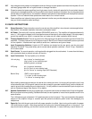
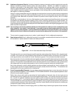
2.34 Input Programming Switches 8-pole mini DIP switches are located on the rear panel—see the rear panel
illustration for details. They come factory set for normal stereo operation (switches 1,2 and 7,8 up). See section
3.5 for other cases.
2.35 Octal Socket For normal operation, nothing should be plugged into the octal socket. It comes from the factory
with a protective label to prevent corrosion of the pins.
2.36 Input Connections The input polarity is as follows:
1/4-inch plug: tip is “minus” or inverting input
ring is “plus” or non-inverting input
barrel is ground, as always
XLR plug: pin 1 is ground, as always
pin 2 is “plus” or non-inverting input
pin 3 is “minus” or inverting input (AES Standard)
Barrier Strip: “GND” is circuit ground
“+” is “plus” or non-inverting input
“-” is “minus” or inverting input
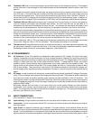
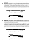
When making unbalanced connections, the barrel of an ordinary two-wire 1/4 inch plug will ground the “plus” side
of the balanced input; XLR plugs will need to have the unused pin grounded inside the plug, and the installer will
need to ground the unused screw on the barrier strip. It is still possible to use the balanced inputs to reject hum
with an unbalanced signal. See Section 3.3 for details.
2.37 Speaker Connections Banana plugs, spade lugs, or bare wire ends can be connected to the 5-way binding posts.
Be sure to observe correct polarity (red/black terminals) for each speaker to insure that all speakers move in the
same direction.
The 1100 features a pair of standard 1/4" headphone jacks on the front panel. They are connected to the speaker
outputs of the amplifier through a resistive pad that prevents excessive power levels from damaging the
headphones.
2.38 Power Up Start with the gain controls off until proper operation is verified. Upon turning on the switch, the power
LED should come on green. After three seconds, the muting circuit should release and turn on the sound. The
amp should now be working, and the Gain controls can be advanced. In case of difficulty consult Section 3.9.