


15
3.7 25 AND 70 VOLT SYSTEMS
3.71 Introduction Commercial sound systems commonly use dozens or even hundreds of speakers for sound
distribution. Special methods for connecting and controlling many separate speakers have been worked out by
commercial sound contractors.
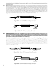
3.72 25 Volt lines 25 volt distribution systems are popular in small to medium sized installations where local codes
require conduit for 70-volt lines.
The Model 1100 amplifier will deliver up to 120 watts directly to 25 volt lines by using the mono-bridge mode.
Please note that, as with any system using the mono-bridge mode, neither side of the speaker line should be
grounded.
The Model 1200 amplifier will deliver up to 150 watts per channel directly to 25 volt lines. The Model 1400 and
1700 have excessively high output voltages and are not recommended for directly driving 25 volt lines.
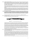
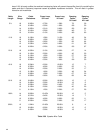
3.73 70 Volt lines All Series One amplifiers may be used with our 70-volt output transformers, the OT-300a and OT-
600, to power 70 volt distribution systems. See the following table for details on transformer model and power
ratings. Consult the transformer Owner’s Manual for additional information on 70 Volt distribution applications.
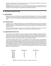
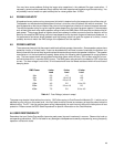
Output Voltage Power,Per
Model Transformer Tap Channel
1100 OT-300a 17 V 70w
1200 OT-300a 25 V 150w
1400 OT-300a 35 V 300w
1700 OT-600 45 V 500w
Table 3.73 70 Volt Output Power
3.74 Low Frequency Rolloff In commercial sound systems, a rolloff below 50 Hz or so is desirable to prevent excess
wasted power at frequencies below the range of the speakers and their small transformers. Contact the QSC Sales
Department regarding the availability of Octal Modules for this application. The roll-off may also be provided by
preceding signal processing equipment, such as EQ’s, active crossovers and mixers.
3.8 PROTECTION FEATURES
3.81 Summary We have ensured that accidents, mistakes, and abuse will have the minimum possible chance of
harming the amplifier or speaker . The major challenge was to do this without impairing the audio performance
into normal loads.
3.82 Short Circuit Protection The active region in a power transistor is surprisingly small—perhaps 1/5 of a inch wide.
This little piece of silicon must control hundreds of watts of power. If not managed properly, this can burn out the
silicon, instantly destroying the transistor.
Under normal conditions, most of the power passes through the transistor, into the speaker, producing useful
power and only some waste heat. If too many speakers (too low of an impedance) are connected, excessive power
will be drawn through the transistor, and more heat will be wasted. If the load impedance drops to zero, which
might happen if the speaker wires are shorted together, then there would be almost no limit to the power drawn
through the transistor, and the waste heat will be so high that the transistor will burn out. This is why solid state
amps need short circuit protection.
The patented QSC “Output Averaging” short circuit protection acts by monitoring the load impedance. As long
as it is within rated limits (above 2 ohms), the amount of waste heat in the power transistors is acceptable, and
full audio power is allowed to continue. If the output impedance is reduced below 2 ohms the instantaneous current
peaks will be limited, but to a fairly high value, which the transistors can handle for a short time; if a strong signal
persists for more than a fraction of a second, the current limit is smoothly cut back to a lower value which the
transistors can handle indefinitely.
The result is full performance into rated loads, ability to handle normal program peaks into marginal loads, and
good protection into short circuits. At no time will the circuit cause abnormal distortion spikes or loss of sound.