


15
PREPARATION
PREPARATION
Connecting Your Equipment
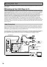
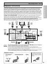
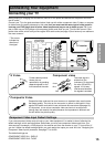
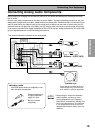
Connecting your TV
Before making or changing the connections, switch off the power and disconnect the power cord from
the AC outlet.
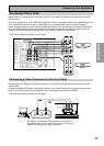
Connect your TV to the jacks as shown below. Hook up with either component video, S video, or compos-
ite video cords (the quality descends in this order) but you must use the same type of video cords to
hook up your DVD player (and all other video components) as you use to hook up your TV. If you
plan to hook up your DVD player with component video cords hook up your TV with them as well. Com-
posite video cords, which look just like regular RCA audio cords (see page 19) but have only one cable are
the most common.
Y
P
B
P
R
Green
Blue
Red
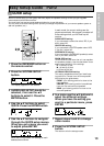
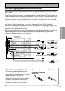
S Video Component video
The video signal is
divided into the
luminance (Y) signal and
the color (PB and PR)
signals. In this way,
interference between
the signals is avoided.
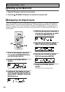
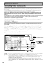
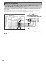
Component Video Input Default Settings
If you use component video cords to hook up your video equipment it is easiest to do so following the
default settings, which are listed below. Remember you must use component video cords from your
video source (for example, a DVD player) to the receiver and from the receiver to your TV (or monitor). If
you don't follow the default settings below you must assign the inputs you used with the "Assigning the
Component Video Inputs" procedure. See page 77 to do this.
The default settings are:
COMPONENT VIDEO IN 1: DVD/LD
COMPONENT VIDEO IN 2: TV/SAT
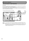
S VIDEO
S video cables produce
clearer picture
reproduction by sending
separate signals for the
luminance and the color.
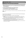
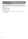
Composite Video
Composite video cords are the most common or standard video cord but also
the lowest quality. The color on the connector is yellow to distinguish it from
regular RCA audio cords which have white and red connectors (see page 19).
It is important to use a true composite video cord and not an audio cord
(though they look exactly the same) because the impedance is different and
this will affect the picture quality.
PCM/
2DIGITAL /
DTS
OUT1
OUT2
IN
R
L
(TV/
SAT)
1
IN
1
IN
2
IN
(CD-R/
TAPE1)
2
IN
3
(DVD/
LD)
IN
4
(CD)
PLAY
PLAY
CD-R/
TAPE1
IN
OUT
IN
OUT
VCR1/
DVR
TV/
SAT
IN
DVD/
LD
IN
SUR-
ROUND
BACK
(DVD/LD)
(TV/SAT)
FRONT
CENTER
SUR-
ROUND
SUB
WOOFER
PRE OUT
MONITOR OUT
P
B
PR
PB
PR
Y
Y
Y
P
B
PR
VCR2
CD
LINE
DIGITAL
AUDIO AUDIO VIDEO
IN
IN
IN
OUT
IN
OUT
VIDEO S VIDEO
MD/
TAPE2
REC
REC
MULTI CH IN COMPONENT VIDEO
OUT
IN
MONITOR OUT
CONTROL
75Ω
ANTENNA
AM LOOP
FM UNBAL
R
L
R
L
L
R
L
R
L
R
ASSIGNABLE
ASSIGNABLE
SUR-
ROUND
BACK
SUR-
ROUND
FRONT
SUB
WOOF-
ER
L
R
L
R
L
R
CEN-
TER
(Single)
TV/monitor
COMPO-
NENT
VIDEO
VIDEO IN
S-VIDEO
Y
P
B
P
R
*The arrows
indicate the
direction of
the signal.