


Simple setup
4
RQTV0141
P
B
P
R
Y
S VIDEO
OUT
COMPONENT
VIDEO OUT
VIDEO
OUT
S-VIDEO
IN
P
B
P
R
Y
S VIDEO
OUT
COMPONENT
VIDEO OUT
VIDEO
OUT
VIDEO IN
COMPONENT
VIDEO IN
P
B
P
R
Y
S VIDEO
OUT
COMPONENT
VIDEO OUT
VIDEO
OUT
AM ANT
LOOP
EXT
2
1
5 -12 m
2
1
AM ANT
LOOP
EXT
4
1
2
3
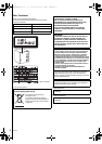
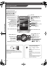
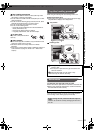
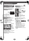
Conserving power
The unit consumes power (approx. 0.9 W) even when it is turned off with [Í] (main unit: [Í/I]). To save power when the unit is not
to be used for a long time, unplug it from the household AC power socket. You will need to reset some memory items after plugging
in the unit.
To household AC power socket
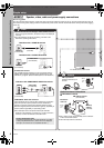
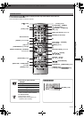
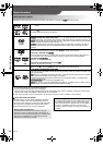
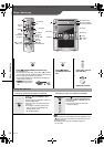
STEP 1 Speaker, video, radio and power supply connections
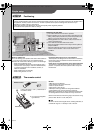
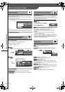
Video
Television with a VIDEO IN terminal
Television with a S VIDEO IN terminal
Television with COMPONENT VIDEO IN terminals
Video cable
(included)
S video cable
(not included)
Video cable
(not included)
Television
(not included)
Television
(not included)
Television
(not included)
COMPONENT VIDEO OUT terminals
These terminals can be used for either interlace or progressive
output and provide a purer picture than the S VIDEO OUT
terminal. Connection using these terminals outputs the color
difference signals (P
B/PR) and luminance signal (Y) separately in
order to achieve high fidelity in reproducing colors.
≥The description of the component video input terminals
depends on the television or monitor (e.g. Y/P
B/PR,Y/B-Y/R-Y,
Y/C
B/CR). Connect to terminals of the same color.
To enjoy progressive video
Connect to the component video input terminals on a 480p
or 576p compatible television. (Video will not be displayed
correctly if connected to an incompatible television.)
≥Do not connect the unit through a video cassette recorder.
Due to copy guard protection, the picture may not be displayed
correctly.
≥Turn the television off before connecting, and refer to the
television’s operating instructions.
S VIDEO OUT terminal
The S VIDEO terminal achieves a more vivid picture than the
VIDEO OUT terminal by separating the chrominance (C) and
luminance (Y) signals. (Actual results depend on the television.)
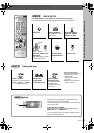
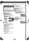
Antenna
AM loop antenna
Stand the antenna up on
its base.
Optional antenna connections
∫ AM outdoor antenna
AM outdoor antenna
(not included)
AM loop
antenna
(included)
Back of the
main unit
≥Run a piece of vinyl wire horizontally across a window
or other convenient location.
≥Leave the loop antenna connected.
Speaker, video, radio and power supply connections
SC-VK650GCSGCTGN.book 4 ページ 2006年4月17日 月曜日 午後5時47分