


9
LTC 2600 Series Section 2 Installation
2.1 Mounting
The multiplexer is supplied as a desktop unit. If desired the unit may be rack mounted using the included rack
mount kit.
2.2 Connecting the Video Multiplexer System
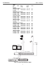
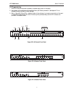
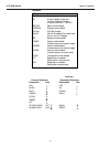
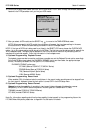
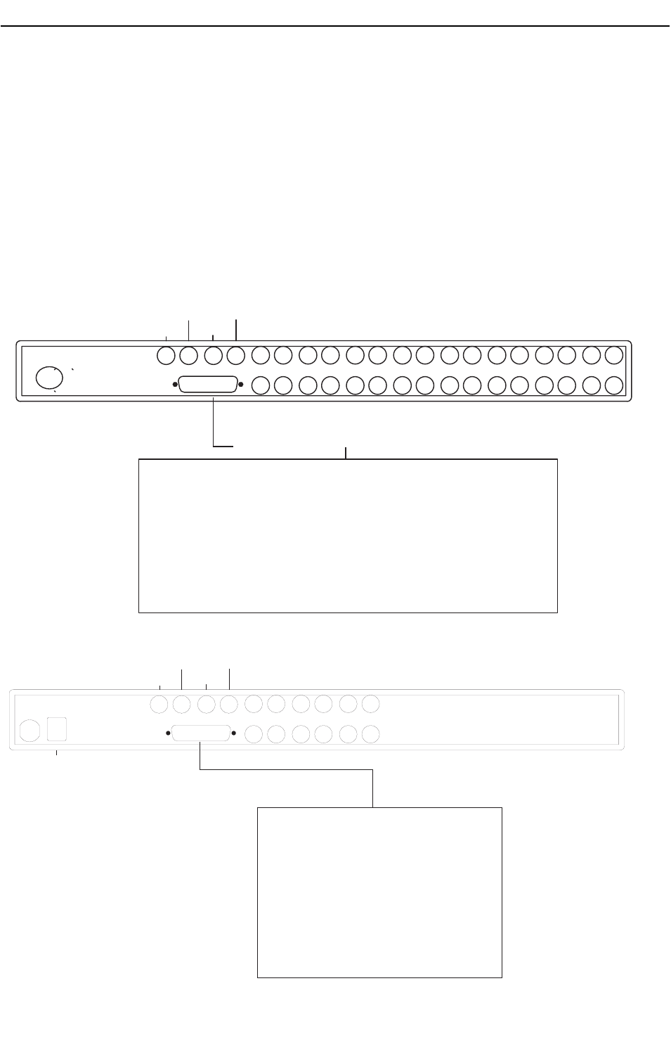
1. Refer to Figures 2A and 2B for details on the input/output connections supplied by the multiplexer.
(Be sure to reference the appropriate drawing for your multiplexer model.)
2. Review the typical installation diagrams provided in Appendix B at the back of the manual, and determine
the number of cameras, monitors, and VCRs to be incorporated into the system.
3. Connect all peripherals (e.g. cameras, monitors,VCRs) to the corresponding inputs/outputs on the multiplexer
rear panel.
SECTION 2: INSTALLING THE VIDEO MULTIPLEXER
16151413121110987654321
MON AMON B
VCR
OUT
VCR
IN
ALARM
3032724-703
VCR IN
VCR Out
Mon B
Mon A
Cameras
1-16
Power
Alarm In/Out (Cable Supplied)
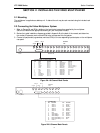
Pin Color Function Pin Color Function
1 Black Alarm 1 14 White/Orange Alarm 14
2 Brown Alarm 2 15 White/Yellow Alarm 15
3 Red Alarm 3 16 White/Green Alarm 16
4 Orange Alarm 4 17 White/Blue Video Loss Relay 1
5 Yellow Alarm 5 18 White/Violet Video Loss Relay 1
6 Green Alarm 6 19 White/Greg Alarm Relay 1
7 Blue Alarm 7 20 Wht/Blk/Brn Alarm Relay 1
8 Violet Alarm 8 21 Wht/Blk/Red Vext Input 1
9 Grey Alarm 9 22 Wht/Blk/Org N/C
10 White Alarm 10 23 Wht/Blk/Yel N/C
11 White/Black Alarm 11 24 Wht/Blk/Grn N/C
12 White/Brown Alarm 12 25 Wht/Blk/Blu Gnd
13 White/Red Alarm 13
Figure 2A: 16-Channel Back Panels
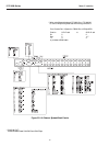
Figure 2B: 6-Channel Back Panels
654321
MON AMON B
VCR
OUT
VCR
IN
ALARM/SDA
KEYBD
VCR IN
VCR Out
M on B
M on A
Key Board
Cameras
1-16
ALARM /SDA
Pin Function
1
2
3
4
5
6
7
8
9
10
11
12
Pin
14
15
16
17
18
19
20
21
22
23
24
25
13
Alarm 1
Alarm 2
Alarm 3
Alarm 4
Alarm 5
Alarm 6
Gnd
Vext Input 1
Alarm Relay 1
Alarm Relay 1
Video Loss Relay 1
Video Loss Relay 1
C ode 1 -
Function
C ode 1 +
Shield
C ode 2 -
C ode 2 +
Shield
C ode 3 -
C ode 3 +
Shield
C ode 4 -
C ode 4 +
Shield
Gnd