11
2.3 Programming
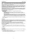
1. When all connections have been successfully completed, apply power to the system.
2. Upon power up, the multiplexer will be using the factory-set default parameters. (See Appendix C for a
complete listing of the Factory Default Settings.)
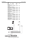
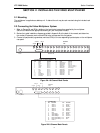
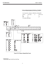
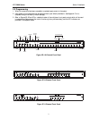
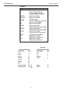
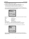
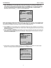
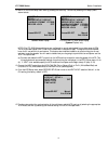
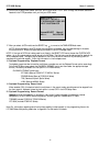
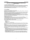
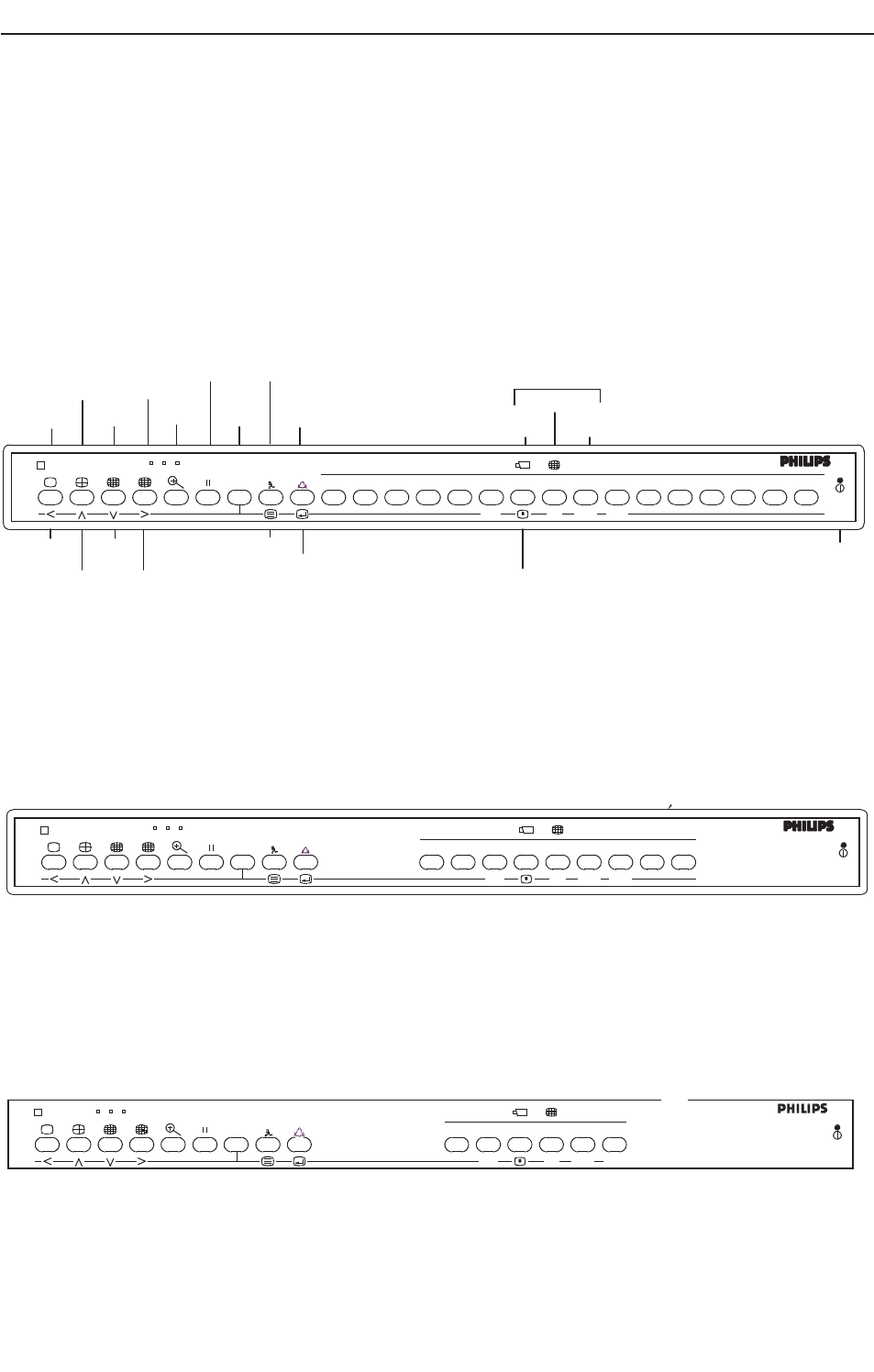
3. Refer to Figures 2D, 2E and 2F for a detailed review of the multiplexer front panel controls which will be used
in programming. Summaries of the control functions (primary and secondary) and the LED indicators are
provided in the adjacent tables.
LTC 2600 Series Section 2 Installation
Video Multiplexer
#
123456789
VCR
SEQ
PLAY REC
ALM
ACT
Video Multiplexer
#
16151413121110
987654321
LEFT
UP
DOWN
RIGHT
FULL
QUAD
MULTI
CAMEO
ZOOM
FREEZE
ALT
ACTION
CLEAR
ALARM
CLEAR
VCR
MON B
SEQ
PLAY
REC
CAMERA
CAMEO
LED INDICATOR
KEYBOARD
POWER LED
MENU
SELECT
ALMACT
Figure 2D: 16-Channel Front Panel
Figure 2E: 9-Channel Front Panel
V id e o M u ltip le x e r
#
12345
.6
VCR
SEQ
PLAY
REC
ACT
ALM
ALT
Figure 2F: 6-Channel Front Panel


