


9
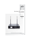
2. PART NAMES AND FUNCTIONS
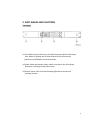
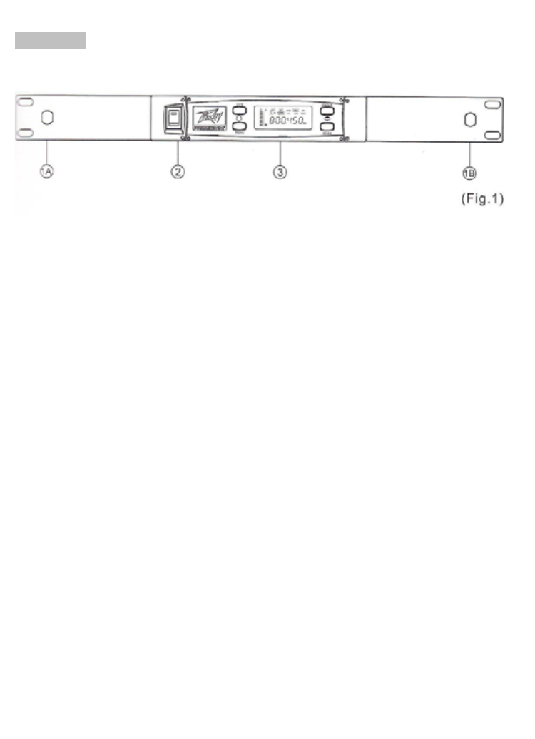
Front Panel:
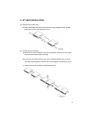
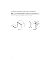
(1) Front Antenna Input Connectors (A and B): located on optional rack-mount
ears: Allows an optional rear-to-front Antenna kit for front antenna
placement on OPTIONAL rack-mount brackets.
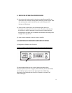
(2) Power Switch and Indicator: When switch is turned on, the red indicator
illuminates, indicating normal power status.
(3) Receiver Panel: Color LCD Panel indicating adjustment controls and
operational status.