Operations Manual, HPA3, Mini Compact Outdoor SSPA 208143 REV - 69
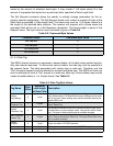
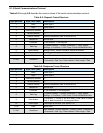
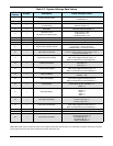
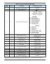
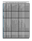
Table 8-9: System Condition Addressing
Data
Address
# Bytes Description Limits and valid values
1 2
Attenuation DAC value
(Read Only in Temp Co Mode)
0 to 4095
2 2 Present Temperature +/- 100
3 2 Fault, Mute, and State Conditions
2-Byte Value
0 fault clear; 1 fault set
0 mute clear; 1 mute set
0 standby state, 1 on line state
0 Ext. Ref, 1 Internal Ref
Lower Byte
Bit 0 = Summary Fault
Bit 1 = High Temp Fault
Bit 2 = Low DC Current Fault
Bit 3 = Low DC Voltage Fault
Bit 4 = External Mute Status
Bit 5 = Internal Mute Status
Bit 6 = Forward RF Fault
Bit 7 = Reference Source
High Byte
Bit 0 = BUC Fault
Bit 1 = Spare Fault
Bit 2 = Auxiliary Fault
Bit 3 = Fiber Fault
Bit 4 = RF Switch Control 1 state
Bit 5 = RF Switch Control 2 state
Bit 6 = Reserved, Always 0
Bit 7 = Unit On Line State
4 2 Present Attenuation Level
1bit per 0.1 dB attenuation
Low Byte: 0 to 150
High Byte: always 0
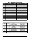
5 2
Present RF Power Level
Output is dBm x 10
0 to 800
6 2 Total DC Current
20 Amp maximum
1 value = 0.1 Amp
7 2 PS2 Regulator DC Voltage
15 Volt maximum
1 value = 0.1 Volt
8 2 PS2 Voltage
15 Volt maximum
1 value = 0.1 Volt
9 2 Transistor Gate Voltage
0 to 10 volt range
Use 2’s compliment integer math
1 value = 0.1 Volt
10 2 PS1 DC Current 1Value = 0.1 Volt
11 2 PS1 Regulator DC Voltage 1Value = 0.1 Volt
12 2 PS1 Voltage 1Value = 0.1V
13 2 External Reference Level 0 to 1023
14 2 Baseplate Temperature +/- 100
15 2
Tempco DAC value
(Read Only in Temp Co Mode)
0 to 4095
Note: Data length must be at least two bytes to form integer with the lower byte sent first. If odd number of bytes is received, the
last byte will be saved as the lower byte of the integer and upper part will be zero.


