Operations Manual, HPA3, Mini Compact Outdoor SSPA 208143 REV - 31
3.3.1.3 Voltage, Current and Temperature Display
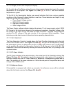
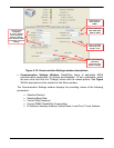
On the right side of the Status window there is a thermometer display that reports the present
temperature of the amplifier. See Figure 3-9, Item [3]. A 20-30°C rise above ambient
temperature is typical.
To the left of the thermometer display are several indicators that show various operating
conditions of the Compact Outdoor Amplifier in real time. These indicators are helpful for any
diagnostic procedures and consist of:
• Power Supply Voltage monitor
• SSPA DC Current monitor
• Regulator Voltage monitor
• Gate Voltage monitor
The Power Supply voltage indicator displays the primary 12 volt power supply output. SSPA
DC Current is the total current drawn by the microwave transistors. Regulator Voltage is the
DC voltage of the drain circuitry that feeds the GaAs transistors. The Gate Voltage indicator
monitors the DC voltage of the gate circuitry of the microwave GaAs transistors. These
indicators provide direct access to the active device operating characteristics.
3.3.1.4 Gain Adjustment
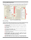
The Gain Attenuation Control is located above the Fault Condition Indicators and to the right
of the Carrier Enable status. See Figure 3-9, Item [4]. The gain can be adjusted by setting
the Attenuation Control. An Attenuation Control of 0 dB is the maximum gain (75 dB) setting
on the amplifier. By setting the Attenuation Control to 20 dB; the gain is set to (55 dB). The
Attenuation Control can be varied by entering the value into the text box, or by clicking on the
up/down buttons.
3.3.1.5 RF Power Indicator
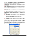
The RF Power indicator is the vertical meter in the central part of the Operation window. See
Figure 3-9, Item [5]. This indicator reports the approximate output power of the amplifier. It
uses the voltage from the RF Power Detector to determine a corresponding power level in
dBm. The accuracy of the power indicator is ±1 dB at the mid-point of the specified band, with
a single CW or QPSK carrier.
3.3.1.6 Reference Source
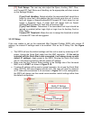
If the amplifier is equipped with a block up converter, the reference source will be indicated
above the fault status window. See Figure 3-9, Item [6].


