Operations Manual, HPA3, Mini Compact Outdoor SSPA 208143 REV - 67
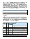
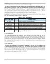
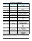
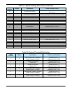
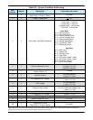
Table 8-7: System Settings Data Values
Data
Address
# Bytes Description Limits and Byte Values
1 1 System Operation Mode
Single Amplifier = 255
1:1 Redundant = 0
2 1 System Hierarchical Address Unit 1= 0; Unit 2= 255
3 1
Unit Start Up State
(in Redundancy)
On Line Amplifier = 255
Standby Amplifier = 0
4 1 Mute State
Mute Clear (Transmit Enable) = 255
Mute Set (Transmit Disable) = 0
5 1
Attenuation Level
(dB down from maximum gain)
[1 bit for every 0.1 dB]
0 dB attenuation = 0
20 dB attenuation = 200
6 1 RESERVE N/A
7 1 Amplifier Network Address 1 to 255
8 1 High Temperature Alarm Threshold 0 to 100 (in
o
C)
9 1 SSPA module Calibration Mode
Temperature Compensated = 255 (normal state)
Tune Mode = 1 (Factory Use Only)
Calibration Mode = 0 (Factory Use Only)
10 1 SSPA Spare Fault Status
Ignore Spare Fault = 255
Fault on value of window on ADC channel = 0 to 1
Fault on External Mute = 8
11 1 SSPA Spare Fault Handling
Minor Fault (no effect on Summary Fault) = 255
Major Fault (Triggers Summary Fault) = 0
Major Fault with Mute (Transmit Disabled) = 1
12 1 Auxiliary Fault Status
Disabled = 255
Fault High = 0
Fault Low = 1
13 1 Auxiliary Fault Handling
Minor Fault (no effect on Summary Fault) = 255
Major Fault (Triggers Summary Fault) = 0
Major Fault with Mute (Transmit Disabled) = 1
14 1 BUC Fault Status
Enabled = 0
Disabled = 255
15 1 BUC Fault Handling
Minor Fault (no effect on Summary Fault) = 255
Major Fault (Triggers Summary Fault) =0
Major Fault with Mute (Transmit Disabled) = 1
16 1 Protocol Select
Serial = 255
IPNET (Ethernet UDP, Web M&C) = 3
SNMP = 4
17 1 Baud Rate Select
9600 = 255
38400 = 0
19200 = 1
4800 = 2
2400 = 3
18 1 Fiber Optic Fault Status
Disabled = 255
Fault on Logic High = 0
Fault on Logic Low = 1
19 1 Fiber Optic Fault Handling
Minor Fault (no effect on Summary Fault) = 255
Major Fault (Triggers Summary Fault) =0
Major Fault with Mute (Transmit Disabled) = 1
20 1 Standby Mode Hot standby=255; Cold standby=0
(continued)
21 1 BUC Reference Autoswitch = 0; External = 1; Internal = 2
22 1 Forward RF Fault Status
Disabled = 255
Low RF Fault Threshold = 0
RF Window @ 10% = 1
RF Window @ 15% = 2
High RF Threshold = 3
Note: Data length must be at least two bytes to form integer with the lower byte sent first. If an odd number of bytes is received, the last byte
will be saved as the lower byte of the integer and the upper part will be zero.


