


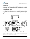
Operations Manual, HPA3, Mini Compact Outdoor SSPA 208143 REV - 17
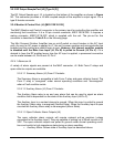
2.2.4.2 Serial I/O Control (J4)
For serial data control of the Compact Outdoor SSPA, a Windows-based Monitor &Control
program is supplied with the amplifier that allows all of the control and alarm functionality over
a serial communication link.
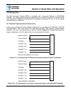
Both RS-232 and RS-485 can be used to communicate with the amplifier. The amplifier
default is to operate on RS-485 but can easily be set to RS-232 by pulling the RS-232/
RS-485 Select line low. This is done by connecting J4-Pin D to J4-Pin V.
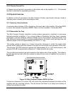
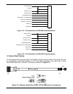
The Mini Compact Outdoor Amplifier may be supplied with a Quick Start Cable in which this
connection is already made. This allows the user to quickly setup the amplifier and verify its
operation. The other side of the cable has a 9-Pin female D connector that mates with most
notebook and desktop personal computers.
Communication links using RS-232 are typically good up to 30 ft. (9 m) in length. Installations
exceeding this length can use the RS-485 mode which will allow serial control up to 4000 ft.
(1200 m).
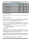
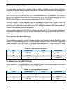
2.2.5 Link Port (J5) [MS3112E10-6S]
The interface connector is used to connect between two Compact Outdoor Amplifiers when
used in a 1:1 redundant system. It is a 6-pin circular connector, MS3112E10-6S. It requires a
mating connector, MS3116F10-6P. A link cable is provided with a 1:1 Redundancy Kit, which
can be purchased separately. See Table 2-3 for a pin-out of this connector.
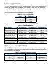
2.2.6 Switch Port (J6) [MS3112E10-6S]
When used in a 1:1 redundant system, the waveguide switch must be connected to the switch
port of each amplifier (MS3112E10-6S). See Table 2-4.
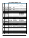
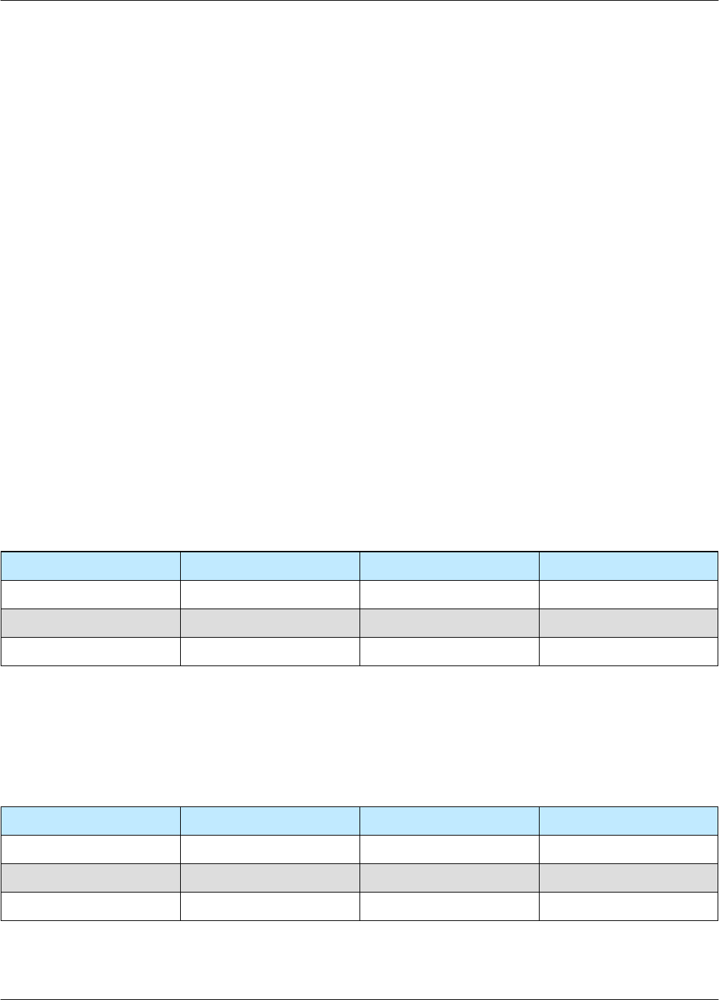
Table 2-3: J5 Link Port Pin-Outs
Pin # Connection Pin # Connection
A Link Out D N/C
B Link In E N/C
C N/C F Ground
Table 2-4: J6 Switch Port Pin-Outs
Pin # Connection Pin # Connection
A N/C D N/C
B N/C E Pos 2
C +28 VDC F Pos 1