


RQTX0064
7
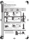
Simple Setup
Turn off all equipment before connection and read the appropriate operating instructions.
Do not connect the AC power supply cord until all other connections are complete.
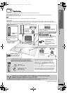
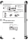
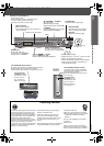
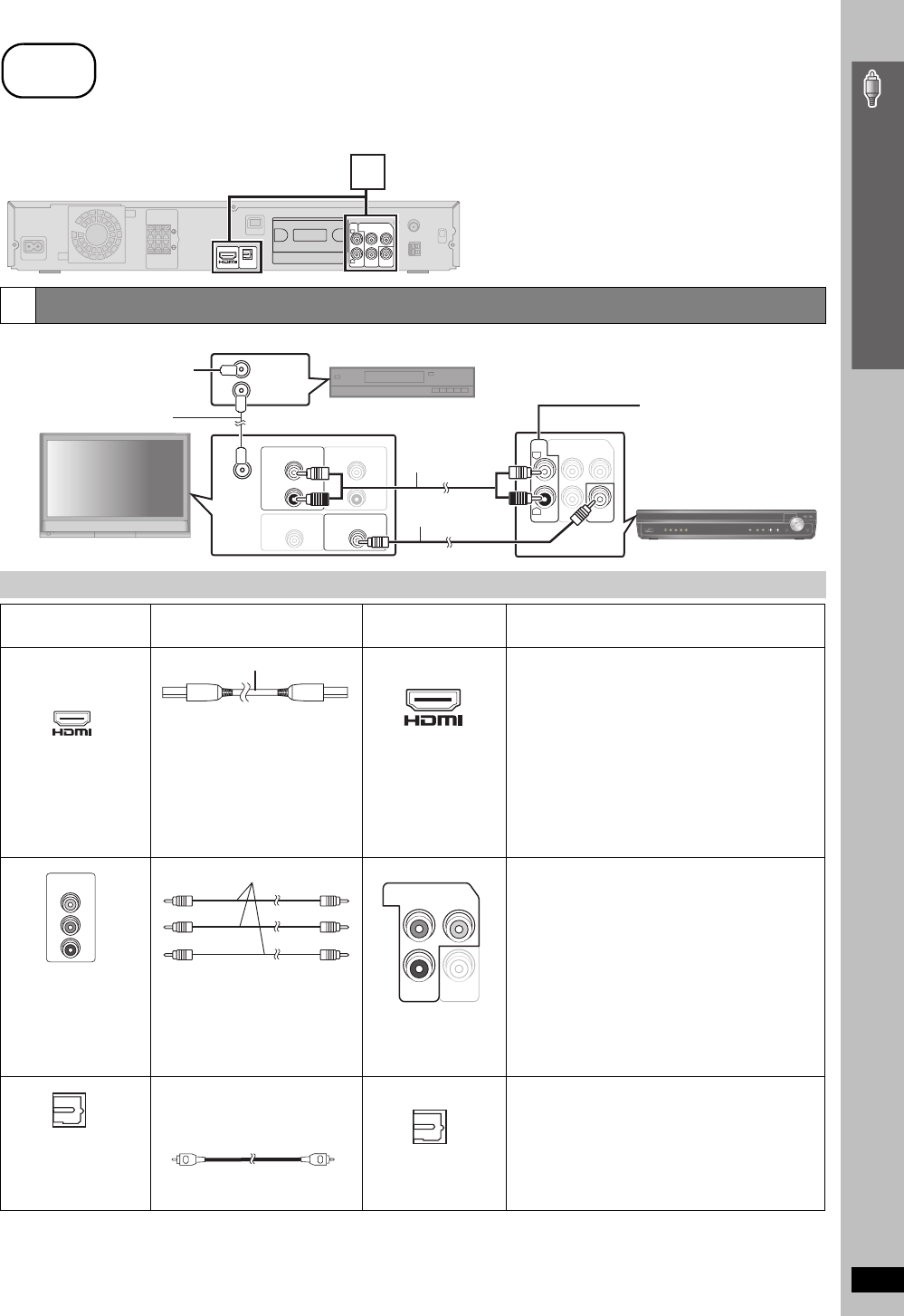
Basic setup example
[Note]
≥Do not make the video connections through the video cassette recorder.
Due to copy guard protection, the picture may not be displayed properly.
≥Only one video connection is required.
(Continued on next page)
1
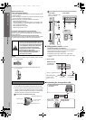
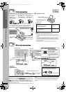
Audio and video connections
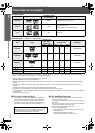
Other connections for improved picture and audio quality
Television terminals
Cables required
(not included)
Main unit terminals Features
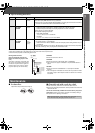
[Note]
≥Non-HDMI-compliant cables
cannot be utilized.
≥It is recommended that you use
Panasonic’s HDMI cable.
Recommended part number:
RP-CDHG15 (1.5 m/4.9 ft),
RP-CDHG30 (3.0 m/9.8 ft),
RP-CDHG50 (5.0 m/16.4 ft), etc.
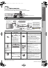
[\\\\\\\\\\\HDMI\\\\\\\\\\\]
This connection provides the best picture quality.
≥Set “Video Mode” to “On” (➜ page 26, “HDMI” menu).
≥Set “Video Output Mode” (➜ page 23, Picture Menu).
EZ Sync “HDAVI Control”
If your Panasonic television is an HDMI control
compatible television, you can operate your television
synchronizing with home-theater operations or vice
versa (➜ page 28, Using the EZ Sync
TM
“HDAVI
Control
TM
”).
≥Make the audio connection (➜ above) when you use
EZ Sync “HDAVI Control” function.
All Panasonic televisions
that have 480p input
connectors are
compatible. Consult the
manufacturer if you have
another brand of
television.
[COMPONENT\VIDEO]
≥Connect to terminals
of the same color.
This connection provides a much purer picture than the
VIDEO OUT terminal.
≥After making this connection, select “Darker” from the
“Black Level Control” in the “Video” menu
(➜ page 26).
To enjoy progressive video
≥Connect to a progressive output compatible
television.
1Set “Video Mode” to “Off” (➜ page 26, “HDMI”
menu).
2
Set “
Video Output Mode
” to “480p”, and then follow
the instructions on the menu screen
(➜ page 23,
Picture Menu).
[PT1050]
[OPTICAL\IN]
This unit can decode the surround signals received
through cable TV box, digital broadcasting or satellite
broadcasts. Refer to your equipment’s operating
instructions for details. Only Dolby Digital and PCM can
be played with this connection.
≥After making this connection, make settings and
select sound effects to suit your digital equipment
(➜ page 34).
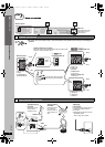
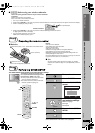
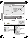
step
3
Cable connections
COMPONENT VIDEO OUT
VIDEO
OUT
P
B
Y
R
P
R
L
AUX
AV OUT
OPTICAL
IN
1
Main unit
(The illustration shows SC-PT1050.)
R
L
AUX
COMPONENT VIDEO OUT
VIDEO
OUT
P
B
Y
R
P
AUDIO OUT
L
R
AUDIO IN
L
R
RF IN
VIDEO INVIDEO OUT
RF OUT
RF IN
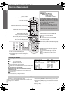
Cable TV box or video cassette recorder (not included)
Main unit
Audio cable
(not included)
You can enjoy audio from your
television, video cassette
recorder or cable TV programs
through this home theater
system by connecting to the
AUX terminals. Select “AUX”
as the source (➜ page 34).
Television (not included)
To your cable TV service or
television antenna
RF cable (not included)
Video cable
(included)
AV IN
HDMI cable
AV OUT
COMPONENT
VIDEO IN
PR
PB
Y
Video cables
COMPONENT VIDEO OUT
VIDEO
OUT
P
B
Y
R
P
OPTICAL OUT
Optical digital audio cable
(not included)
≥
Do not bend sharply when connecting
.
OPTICAL
IN
Cable connections
0064 En_p03-15.fm Page 7 Wednesday, January 31, 2007 12:26 PM