


46
CQ-SRX7000U
37
E
N
G
L
I
S
H
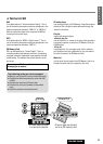
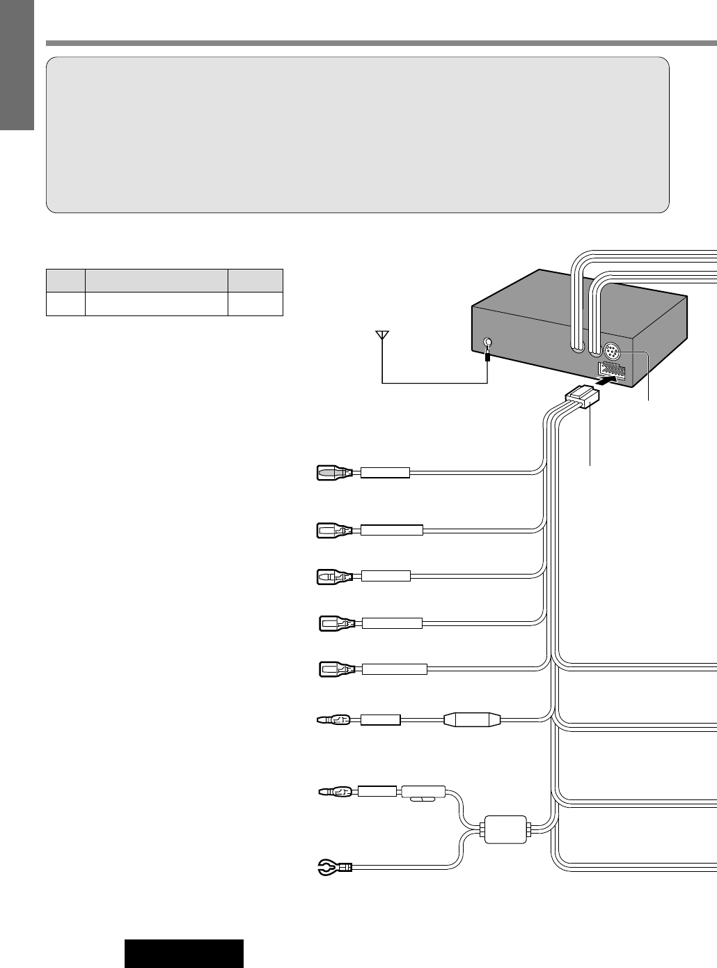
BATTERY 10A
ACC
TWIN CD·C-CONT
NAVI MUTE
ANT-CONT MAX 0.1A
ILLUMINATION
AMP-CONT MAX 0.1A
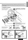
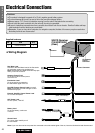
Navi Mute Lead
Connect to the Navi Mute Lead of the Panasonic
car navigation system (not available yet).
Note: Insulate the Navi Mute Lead with vinyl tape
when you do not connect it.
Antenna Control Cord
To the auto antenna control power
cord of the car
Illumination Lead
To the power line connected to
the side marker lights of the car
External Amplifier Control Power Lead
To an external amplifier
ACC Power Lead
To ACC power, +12V DC
(Orange)
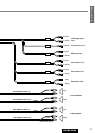
CD Changer
Control
Connector
Antenna
e Power Connector
(Blue)
(Yellow)
Fuse (10A)
(Red)
Resistor (1kΩ)
(Black)
(Orange / white stripe)
(Brown / white stripe)
(Blue / white stripe)
Battery Lead
To the car battery, continuous
+12V DC
Ground Lead
To a clean, bare metallic part of
the car chassis
Dual CD Changer Control Lead (not used)
Note: Insulate the Dual CD Changer Control
Lead with vinyl tape.
Note: If your car does not have a power line connected to the side marker lights of the car, leave the illumination lead disconnected.
SD/CD Receiver
CQ-SRX7000U
(Rear)
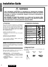
Cautions:
¡This product is designed to operate off a 12 volt, negative ground battery system.
¡To prevent damage to the unit, be sure to follow the connection diagram bellow.
¡Remove approx. 1/4” (5 mm) of protective covering from the ends of the leads before connecting.
¡Do not insert the power connector into the unit until the wiring is completed.
¡Be sure to insulate any exposed wires from a possible short-circuit from the car chassis. Bundle all cables and keep
cable terminals free from touching any metal parts.
¡Remember, if your car has a drive computer or a navigation computer, the data of its memory may be erased when
the battery terminals are disconnected.
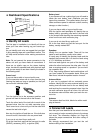
Electrical Connections
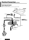
Supplied hardware
No. Item Q’ty
e Power Connector 1
❏ Wiring Diagram