17
Connecting External Devices
• Before making any connections, read the manuals
supplied with your other components.
• Don’t connect the power cord until you’ve completed
and double-checked all connections.
Connection Color Coding
RCA-type audio connections are usually color-coded:
red and white. Use red plugs to connect right-channel
audio inputs and outputs (typically labeled “R”). Use
white plugs to connect left-channel audio inputs and out-
puts (typically labeled “L”).
• Push plugs in all the way to make
good connections (loose connec-
tions can cause noise or malfunc-
tions).
• To prevent interference, keep
audio cables away from power
cords and speaker cables.
Optical Digital Jacks
The CD receiver’s optical digital jacks have shutter-type
covers that open when an optical plug is inserted and
close when it’s removed. Push plugs in all the way.
Caution: To prevent shutter damage, hold the optical
plug straight when inserting and removing.
Note:
Do not place objects on the unit as they may interfere
with proper ventilation.
A connecting cable is not included with this unit.
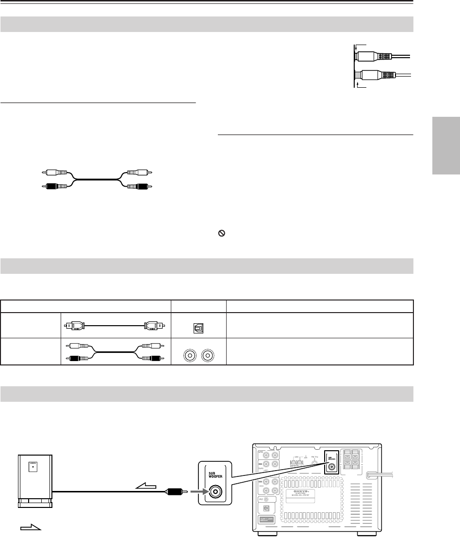
The CD receiver has a SUBWOOFER PRE OUT jack. Connect an active subwoofer (a subwoofer that contains an
amplifier).
About Connections
Left (white)
Right (red)
Analog audio
Left (white)
Right (red)
Right!
Wrong!
Cables & Jacks
Cable Jack Description
Optical digital
audio cable
This cable carries digital audio.
Analog audio
cable (RCA)
This cable carries analog audio.
OPTICAL
R
L
Connecting a Subwoofer
SPEAKERS
PRE
OUT
ANTENNA
R
L
REMOTE
CONTROL
OPTICAL
IN
OUT
IN
IN
OUT
R
L
R L
DIGITAL OUT
PRE
OUT
: Signal flow
Active subwoofer
(with a built-in amplifier)
CD receiver


