


6
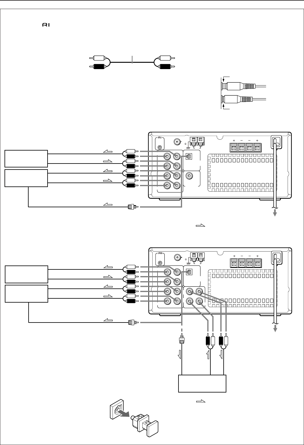
Audio equipment connections
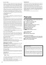
• Do not connect the AC power cord (mains lead) to the wall outlet (the mains) until you have completed all the other connections
including the
connections on page 7, and the speaker connections on page 8.
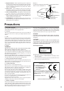
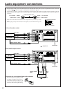
• On each pair of connectors, a red connector (marked R) corresponds to the right channel, and a white connector (marked L) to the left
channel. Connect white plugs of audio connection cables to L connectors and connect red plugs of audio connection cables to R
connectors .
• Please refer to the instruction manual for each component when you make any connec-
tions.
• Insert the plug securely. If the connection is incomplete, noise or malfunction may result.
U.S. and Canadian models
Asian and European models
To L connector , (White)
To R connector , (Red)
Audio connection cable
(White) / To L connector
(Red) / To R connector
Improper connection
Insert completely
L
RL
RL
REMOTE
CONTROL
OPTICAL
SPEAKERS
TAPE
CDR
DIGITAL
OUTPUT
SUBWOOFER
PRE OUT
ANTENNA
AM
FM
75
R
OUT
(
REC
)
(
PLAY
)
IN
OUT
(
REC
)
(
PLAY
)
IN
L
RL
RL
REMOTE
CONTROL
SPEAKERS
TAPE
CDR MD
ANTENNA
AM
FM
75
DIGITAL
OUTPUT
R
OUT
(
REC
)
(
PLAY
)
IN
OUT
(
REC
)
(
PLAY
)
IN
OUT
(
REC
)
(
PLAY
)
IN
RL
OPT
I
CAL
Stereo cassette
tape deck
CD recorder
MD recorder
Stereo cassette
tape deck
CD recorder
INPUT (REC)
OUTPUT (PLAY)
INPUT (REC)
OUTPUT (PLAY)
DIGITAL OPTICAL INPUT
: Signal flow
INPUT (REC)
OUTPUT (PLAY)
INPUT (REC)
OUTPUT (PLAY)
DIGITAL OPTICAL INPUT
OUTPUT
(PLAY)
: Signal flow
INPUT
(REC)
DIGITAL OPTICAL
INPUT
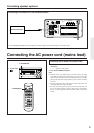
To wall outlet
To wall outlet
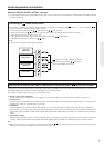
Protective cap for the optical digital audio connector
• Remove the protective cap before you use
the OPTICAL DIGITAL OUTPUT con-
nector. Please retain it for future use. If
you do not use the optical digital audio
connector, make sure to replace the cap.