


User Guide 6ProFire 2626
Hardware Controls and Connectors
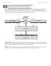
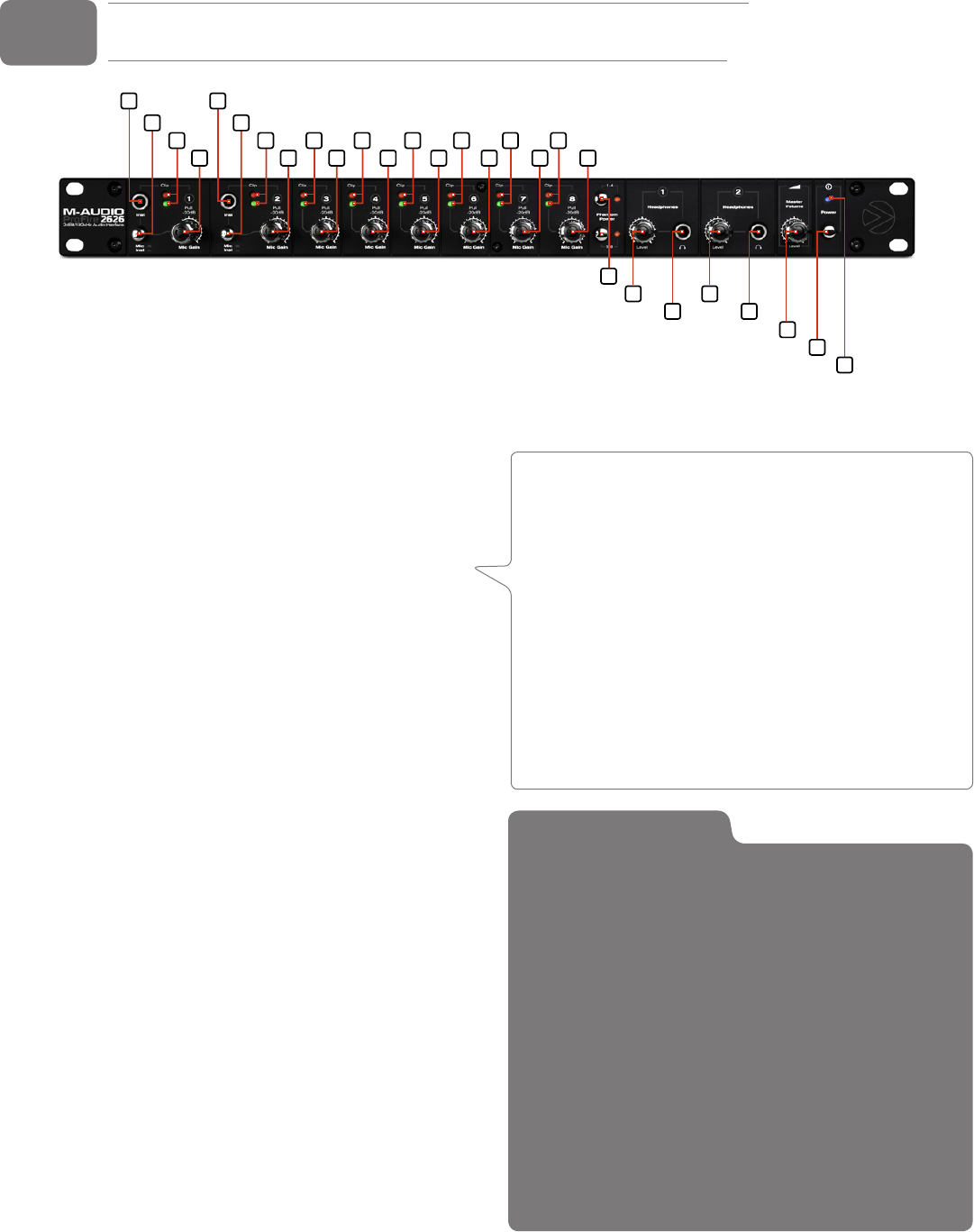
Front Panel
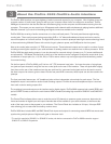
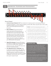
1. Instrument Inputs (Channels 1/2): These unbalanced 1/4” jacks are used for connecting high impedance
instrument-level signals (i.e., electric guitars and basses) to ProFire 2626. When using these inputs, make sure that
the Mic/Inst (2) button is set to its “in” position in
order to route the associated instrument input to
the preamp.
2. Mic/Inst Buttons: These buttons determine
whether the channel’s XLR input (rear-panel
combo jack) or the 1/4” instrument input (on the
front panel) will be routed to the preamp. When
this button is set to the “out” position, the combo
jack’s XLR connection will be active and the front
panel input will be ignored. Conversely, when this
button is set to the “in” position, the channel’s
1/4” front panel input will be active and the combo
jack’s XLR connection will be ignored.
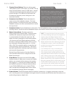
3. Signal/Clip Indicators: The green LED indicates
the presence of a signal at the corresponding analog
input while the red LED indicates “clipping” or
distortion at the input. Use these LED meters to set
levels for the eight analog inputs.
4. Gain Adjustment Knobs / 20dB Pads: These
are dual function knobs that are used to adjust the
preamp gain as well as to engage a 20dB pad. Turn
this knob clockwise to increase the input gain for a
channel. Pull the knob to the “out” position to engage
a 20dB pad or leave the knob in the “in” position to
allow signals to bypass the pad.
5
1
8
9
5
2
4
3
1
2
4
3
4
3
4
3
4
3
4
3 3
4
4
3
6
7
6
7
10
Setting Gain Levels
To set gain levels for an analog input, begin by turning
the Gain Adjustment Knob (4) for that channel fully
counter-clockwise. While the sound source is playing at
its loudest levels, slowly turn the knob clockwise until the
red clip indicator (3) begins to illuminate. Then, turn the
knob counter-clockwise until the clip indicator no longer
illuminates. At this point, you should be ready to record with
the optimum gain setting.
Please keep in mind that the red LED indicates that your
input is clipping (distorting) digitally. This is not the same
kind of analog-style distortion found on guitar amplifiers and
stomp boxes. Digital distortion is generally considered to be
harsh and unmusical and it is recommended that you use
these LED meters to avoid this type of clipping.
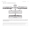
NOTE: The 1/4” line input section of the combo
connector (on the rear of the interface) is never sent to
the preamp, however, the interface does sum the 1/4”
line-level portion of the combo jack and front-panel
instrument-level input. While the summing of these two
1/4” inputs does not affect either input’s impedance or
signal level, it does make it possible to record audio
from both inputs simultaneously. If you have connected
a line-level device to the rear of the interface but only
intend to record from the corresponding instrument
input on the front, please make sure that the connected
device is not outputting any audio (or is powered off).