User Guide 41ProFire 2626
Configuring the Mixer, Router, and Settings tabs
Setting up the DSP Mixer:
The default input channel configuration of the DSP Mixer should work well for most recording scenarios (including
this one). You can verify and/or change the mixer input assignments by clicking the downward arrow ( ) at the
top of each input channel and making your selection from the drop-down menu that appears. The input channels
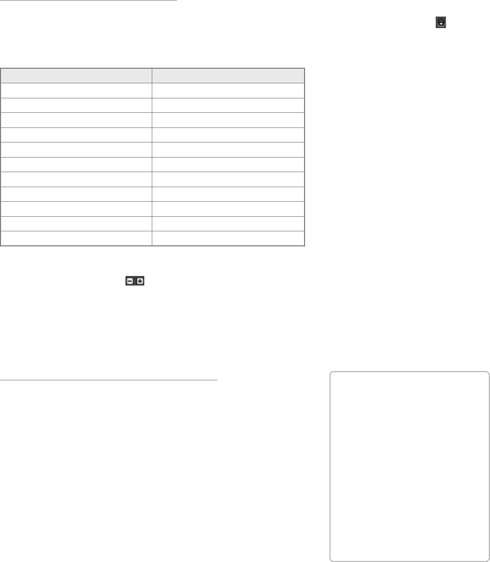
of the DSP Mixer should be assigned as shown in the table below:
DSP Mixer Input Channel Input Channel Source
Mixer Input Channel 1 Analog 1
Mixer Input Channel 2 Analog 2
Mixer Input Channel 3 Analog 3
Mixer Input Channel 4 Analog 4
Mixer Input Channel 5 Analog 5
Mixer Input Channel 6 Analog 6
Mixer Input Channel 7 Analog 7
Mixer Input Channel 8 Analog 8
(Digital I/O not used in this example) (Digital I/O not used in this example)
Mixer Input Channel 17 SW Return 1
Mixer Input Channel 18 SW Return 2
Since we will be setting up two headphone mixes, we will need to see the knobs for Aux Send 1 and Aux Send 2.
Use the “-” and “+“ buttons ( ) on the right side of the mixer to hide unnecessary Aux Sends (i.e., Aux Sends
3-8) or to show the first two Aux Sends (in case the Aux Send 2 knobs have been hidden).
If you would like to name your mixer input channels, you can double-click the numbers listed along the bottom of
the mixer and enter more useful descriptions for each channel. For example, “1” can be renamed “Guitar”, “2” can
be changed to “Vocals”, and so on.
Routing the DSP Mixer outputs:
We will be using the faders and aux send knobs of the DSP Mixer to
create customized cue mixes for the guitarist/vocalist, percussionist, and
the recording engineer. To make sure all of your outputs are correctly
routed, go to the Router tab in the Control Panel:
1. Open the drop-down menu under Analog Out 1/2 and select
“Aux Send 1.”
2. Open the drop-down menu under Analog Out 3/4 and select
“Aux Send 2.”
3. Open the drop-down menu under Analog Out 5/6 and select
“Mixer Out.”
Tip: If the recording engineer
wishes to hear the output of
the audio application instead
of the DSP Mixer, Analog Out
5/6 can be changed from “Mixer
Out” to “SW Return 1/2.” In this
scenario, your audio application’s
mix—including all of its plug-in
effects—is heard. This may be
the desired monitoring method if
the engineer does not require the
extremely low latency of the
DSP Mixer.


