


9
ENGLISH
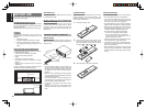
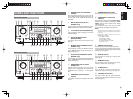
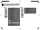
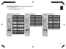
!0 Subwoofer Output
Connect this jack to the line level input of a powered
subwoofer. If an external subwoofer amplifi er is used,
connect this jack to the subwoofer amplifi er input.
If you are using two subwoofers, either powered or
with a 2 channel subwoofer amplifi er, connect a “Y”
connector to the subwoofer output jack and run one
cable from it to each subwoofer amplifi er.
!1 7.1 CHANNEL or AUX2 INPUT
By connecting a DVD Audio player, Super Audio CD
multichannel player, or other components that has a
multichannel port, you can playback the audio with
5.1 channel or 7.1 channel outputs.
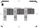
!2 Multiroom Outputs (SR5002 only)
These are the audio output jacks for the Multi zone
(Multi room).
Connect these jacks to optional audio power amplifi ers
to listen the source selected by the multiroom system
in a remote room.
!3 REMOTE CONT. IN/OUT terminals
Connect to a Marantz component equipped with
remote control (RC-5) terminals.
!4 AUDIO IN/OUT (CD, TAPE, CD-R,
TV, DVD, VCR, DSS)
These are the analog audio inputs and outputs.
There are 6 audio inputs (4 of which are linked
to video inputs) and 3 audio outputs (1 of which
are linked to video outputs). The audio jacks are
nominally labeled for cassette tape decks, compact
disc players, DVD players and etc.... The audio inputs
and outputs require RCA-type connectors.
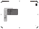
!5 DIGITAL INPUT
(SR4002 : Dig.1 - 4, SR5002 : Dig.1-5)
/ OUTPUT (optical)
These are the digital audio inputs and outputs.
The SR4002 has 2 digital inputs with coaxial jacks, 2
with optical jacks.
The SR5002 has 2 digital inputs with coaxial jacks, 3
with optical jacks.
The inputs accept digital audio signals from a CD,
DVD, or other digital source component.
For digital output, this is 1 optical output.
The digital outputs can be connected to MD recorders,
CD recorders, or other similar components.
!6 HDMI INPUT/OUTPUT
The SR4002 has 2 HDMI inputs and 1 HDMI output.
The SR5002 has 3 HDMI inputs and 1 HDMI output.
The input function can be selected from the
OSD
menu system
. (See page 27)
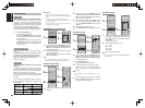
!7 DC TRIGGER output terminal
(SR5002 only)
Connect a device that needs to be triggered by DC
under certain conditions (screen, power strip, etc…)
Use the system OSD setup menu to determine the
conditions by which these jack will be active.
Note:
This output voltage is for (status) control only, It is not
suffi cient for drive capability.
!8 FLASHER IN
(Flasher input terminal) (SR5002 only)
These terminals are to control the unit from each
zone. Connect the control signal from a Keypad, etc.
!9
SPEAKER C SELECTOR SWITCH
(SR5002 only)
The terminals can be used to connect a third set of
speakers by setting the SPEAKER C selector switch
to ON. For connection and use, see page 24.
@0
XM antenna terminal (SR5002 only)
Plug the XM Mini-Tuner and Home Dock into XM
terminal.