


25
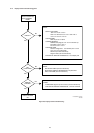
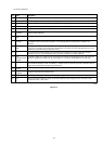
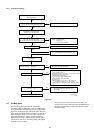
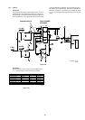
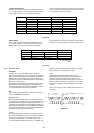
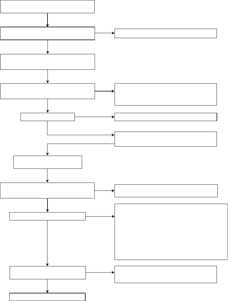
8.2.2 Troubleshooting P816
Figure 8-18
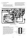
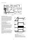
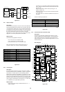
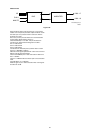
8.3 CD Main Board
The CD main board is built around the compact disc
mechanism VAM1250 and a loader 1250. The CDM delivers
diode signals and an unequalised high frequency signal. These
signals are necessary inputs for the decoder CD10. Based on
these signals the decoder will control the disc. The decoder is
able to control the sledge, focus motor, radial motor and turn
table. When everything is "locked", the decoder delivers a
digital output according to IEC958 standard, subcode to the
microprocessor and I2S for reproducing analog audio signals
by means of a D/A converter.
The microprocessor controls the CD10 and is slave of the
master processor on the CDR main board in the DR6050. Both
processors communicate via a DSA connection (data, strobe
and acknowledge).
YES
OK
Connect the mains inlet to a mains
isolated variac
Check the functionality of the following components :
F820, R819, C820, L820, D802, C821
Check Vcc on pin 1 Q810
Vcc = 12V...... 16V
Is power supply ticking?
Check start circuit and Vcc supply:
R823, R834, C829, D829, R829, R811, C811
Replace Q810
Power supply OK
Power supply unit OK
OK
NOK
NOK
OK
OK
Check the path of the other faulty voltage(s)
Power supply is OK
Check : - CDR main board
- Display assy
- CD main board for DR6050
Check DC voltages
+5V, +12V, -8V, VFTD (-35V),VDC1-VDC2 (3V8)
Check the +5V and +12V
Disconnect powersupply unit from CDR main board
Connect dummy load resistors 10W,
15 ohm at +5V, +12V and ground
Check DC voltages
These voltages might be somewhat higher than specified
+5V, +12V, -8V, VFTD, VDC1-VDC2
OK
+5V : check D856, C857, L856, C859
+12V : check D866, C867, L867, R866, D868, C869
±1.41 x Vin AC
Turn input voltage up and check voltage across C821,
this voltage should be
NOK
OK
Check fuse F820 and
replace if necessary
OK
NO
Load on secondary output
Overvoltage protection : L832, D814, C814, R814, R815, R816
Oscillator voltage on pin 10 of Q810 :
check C802, R810replace Q810
Drive circuit : gate voltage of MOSFET Q825
components R812, R813, C813, R825
Regulation circuit
- Measure voltage on pin 6 of Q810 with oscilloscope
- If > 2.5V check the regulation circuit : Q810, D881
R881- R885, C881, C882, R804 - R806, R809, C804, C809
Check :
NOK
CL 96532076_037.eps
290799