


23
is switched off when the current sense level exceeds the level
at the output of the error amplifier.
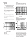
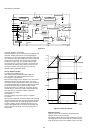
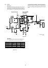
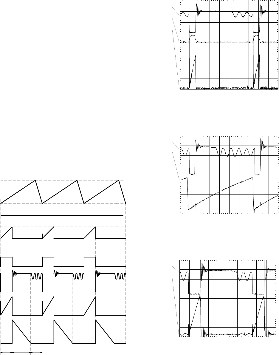
TimeON phase : A drain current will flow from the positive
supply at pin 2 of the transformer through the transformer's
primary winding, the MOSFET and Rsense to ground. As the
positive voltage at pin 2 of the transformer is constant, the
current will increase linearly and create a ramp dependent on
the mains voltage and the inductance of the primary winding. A
certain amount of energy is stored in the transformer in the form
of a magnetic field. The polarity of the voltages at the
secondary windings is opposite to the primary winding so that
the diodes are non-conducting in this phase.
TimeDIODE phase : When the MOSFET is switched off,
energy is no longer supplied to the transformer. The inductance
of the tranformer now tries to maintain the current which has
been flowing through it at a constant level. The polarity of the
voltage from the transformer therefore reverses. This results in
a current flow through the transformer's secondary winding via
the now conducting diodes, electrolytic capacitors and the load.
This current is also ramp shaped but decreasing.
TimeDEAD phase : when the stored energy has been supplied
to the load, the current in the secondary windings stops flowing.
At this point, the drain voltage of the MOSFET will drop to the
voltage of C821 with a ringing caused by the drain-source
capacitance with the primary inductance.
The oscillator will start a next cycle which consists of the above
described three phases. The time of the different phases
depends on the mains voltage and the load.
TimeDEAD is maximum with an input of 400VDC and a
minimum load. It will be zero with an input of 100VDC and an
overload.
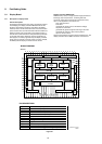
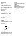
Figure 8-15 ‘Regulation’
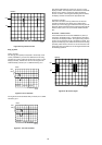
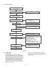
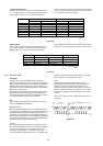
Figure 8-16 ‘Oscillograms’
Vosc
Idiodes
Vgate
Vdrain
Idrain
Vsense
Vcomp
0
V2
V1
Ton Tdiode Tdead
CL 96532076_034.eps
290799
PM3394B
ch2
ch3
ch1
CH1 2
CH2
CH3 2 V~ ALT MTB5.00us- 0.90dv ch1-
1
2
3
T
ch1 : Drain voltage
ch2 : Drain current
ch3 : Gate voltage
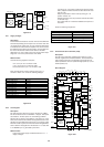
PM3394B
ch3
ch1
CH1 1
CH3 50mV~ ALT MTB5.00us- 0.90dv ch1-
1
3
T
ch1 : Drain voltage
ch2 : Oscillator voltage
PM3394B
ch3
ch1
CH1 1
CH3 20mV~ ALT MTB5.00us- 0.90dv ch1-
1
3
T
ch1 : Drain voltage
ch3 : Sense voltage
CL 96532076_033.eps
290799