


28
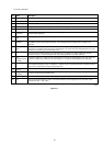
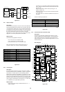
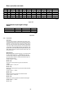
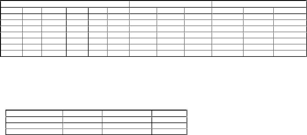
Motor controller truth table
Figure 8-26
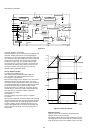
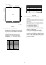
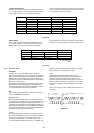
Hall-elements input signal voltage
levels
Figure 8-27
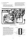
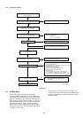
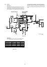
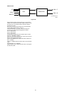
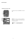
8.3.6 Tray Control
Description
The tray control consists of a TDA7073A power driver (7021)
controlled by the processor 7202 via pin 19 TRAYIN and pin 20
TRAYOUT. If pin 20 is low and pin 19 high, the TRAY+ signal
at pin 16 of 7021 is forced to +8V and the TRAY- signal at pin
13 of 7021 to GND : the tray will open. If pin 20 is high and pin
19 low, TRAY+ becomes GND and TRAY- becomes +8V : the
tray will close. If pin 19 and 20 of the processor have the same
value, TRAY+ and TRAY- will have the same value as well : the
tray stops moving.
Measurements
Keep procesor 7202 in reset by forcing pin 7 of connector 1208
to +5V. Connect a load of 15 , 7W between pin 3 and 4 of
connector 1002. Check the voltage over the load with TRAY+
(pin 3) as positive reference. Check also the levels of pins 19
and 20 of the processor.
U TRAY+,TRAY- = <100mV
Pin 20 = +5V
Pin 19 = +5V
Force pin 20 of the processor to ground, and check the
voltages.
U TRAY+,TRAY- = -6.5V( 10%
Pin 20 = +0V
Pin 19 = +5V
Force pin 19 of the processor to ground as well and check the
levels again.
U TRAY+,TRAY- = <100mV
Pin 20 = +0V
Pin 19 = +0V
Release pin 20 of the processor and check the levels.
U TRAY+,TRAY- = 6.5V( 10%
Pin 20 = +5V
Pin 19 = +0V
Release pin 19 of the processor and check the levels again:
U TRAY+,TRAY- = <100mV
Pin 20 = +5V
Pin 19 = +5V
Input conditions conn 1006 pin Outputs conn 1006 Test points on driver
684 732 9 10 11 18 17 16
U+ U- V+ V- W+ W- UCOIL VCOIL WCOIL HALL_U HALL_V HALL_W
L M H M M M 6V 0V 0V 0V 5V
H M L M M M 0V 6V 6V 5V 0V
M M L M H M 0V 6V 0V 0V 5V
M M H M L M 6V 0V 6V 5V 0V
H M M M L M 0V 0V 6V 5V 0V
L M M M H M 6V 6V 0V 0V 5V
CL96532086_055.eps
080999
Input voltage Level Tolerance Unit
H2.80.1V
M2.50.1V
L2.20.1V
CL96532086_056.eps
080999